
Page 364 - Basic Electrical Engineering
P. 364
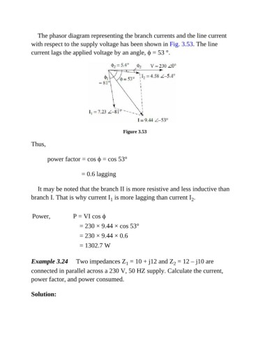
The phasor diagram representing the branch currents and the line current
               with respect to the supply voltage has been shown in Fig. 3.53. The line
               current lags the applied voltage by an angle, ϕ = 53 °.


                                                          Figure 3.53

               Thus,


                         power factor = cos ϕ = cos 53°


                                              = 0.6 lagging


                  It may be noted that the branch II is more resistive and less inductive than
               branch I. That is why current I  is more lagging than current I .
                                                                                         2
                                                    1


                Power,             P = VI cos ϕ
                                      = 230 × 9.44 × cos 53°

                                      = 230 × 9.44 × 0.6

                                      = 1302.7 W


               Example 3.24     Two impedances Z  = 10 + j12 and Z  = 12 – j10 are
                                                           1
                                                                                 2
               connected in parallel across a 230 V, 50 HZ supply. Calculate the current,
               power factor, and power consumed.


               Solution: