
Page 361 - Basic Electrical Engineering
P. 361
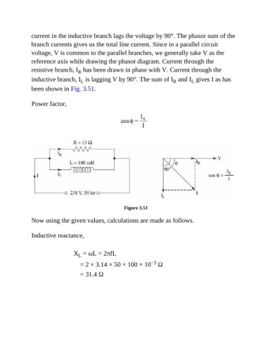
current in the inductive branch lags the voltage by 90°. The phasor sum of the
               branch currents gives us the total line current. Since in a parallel circuit
               voltage, V is common to the parallel branches, we generally take V as the

               reference axis while drawing the phasor diagram. Current through the
               resistive branch, I  has been drawn in phase with V. Current through the
                                     R
               inductive branch, I  is lagging V by 90°. The sum of I  and I  gives I as has
                                                                                R
                                                                                         L
                                      L
               been shown in Fig. 3.51.

               Power factor,


                                                          Figure 3.51

               Now using the given values, calculations are made as follows.


               Inductive reactance,


                                   X  = ωL = 2πfL
                                     L
                                                                      −3
                                      = 2 × 3.14 × 50 × 100 × 10  Ω
                                      = 31.4 Ω