
Page 543 - Basic Electrical Engineering
P. 543
N is less than N , and hence K < 1.
1
2
6.6 TRANSFORMER ON NO-LOAD
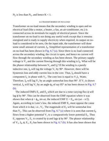
Transformer on no-load means that the secondary winding is open and no
electrical load (like a motor, a heater, a fan, an air-conditioner, etc.) is
connected across its terminals for supply of electrical power. Since the
transformer on no-load is not doing any useful work except that it remains
energized and is ready to supply electricity when required, its output on no-
load is considered to be zero, On the input side, the transformer will draw
some small amount of current, I . Simplified representation of a transformer
0
on no-load has been shown in Fig. 6.7 (a). Since there is no load connected
across the secondary winding, the circuit is open, and hence no current will
flow through the secondary winding as has been shown. The primary supply
voltage is V and the current flowing through this winding is I . What will be
1
0
the phasor relationship between V and I ? If the winding is a purely
1
0
inductive one, I will lag the voltage V by 90°. However, there will be
0
1
hysteresis loss and eddy current loss in the core. Thus, I should have a
0
component I in phase with V . The core loss is equal to V I Watts.
C
1 C
1
Therefore, I will lag V by an angle somewhat less than 90°. If V is shown
0
1
1
vertical, I will lag V by an angle ϕ of say 85° as has been shown in Fig. 6.7
0
0
1
(b).
The induced EMFs E and E which are due to a time-varying flux ϕ will
1
2
lag ϕ by 90°. This can be observed from the EMF equation where it was
shown that when ϕ = ϕ sin ωt, the induced EMF E = E sin (ωt – π/2).
m
m
Again, according to Lenz’s law, the induced EMF E must oppose the cause
1
from which it is due, i.e., V . The magnitude of E will be somewhat less
1
1
than V . This can be observed from Fig. 6.7 (a) where it is seen that current I 0
1
flows from a higher potential V to a comparatively lower potential E . Thus
1
1
E opposes V , E is created by ϕ and lags ϕ by 90°. The phasor relationship
1
1
1
of V , I , ϕ, E , E has been shown in Fig. 6.7 (b). It has also been shown that
0
1
2
1