Page 544 - Basic Electrical Engineering
P. 544

I  can be resolved into two components I  and I , where I  is in phase with ϕ
                                                                         c
                                                                                     m
                                                                 m
                0
               and is responsible for producing ϕ. This I  is also called the magnetizing
                                                                 m
               current because this current magnetizes the core, i.e., produces the required
               flux in the core. I  is equal to I  sin ϕ . I  is equal to I  cos ϕ . Therefore,
                                                            0
                                                     0
                                    m
                                                                                0
                                                                                        0
                                                                c
                            . The no-load power input W  is equal to V  I  cos ϕ  which
                                                               0
                                                                                1 0
                                                                                           0
               equals V  I . The induced EMF in the secondary winding, i.e., E  has been
                                                                                             2
                          1 c
               shown lagging flux ϕ by 90°. It has been assumed that N  > N , and hence E                  2
                                                                                   2
                                                                                          1
               > E .
                    1


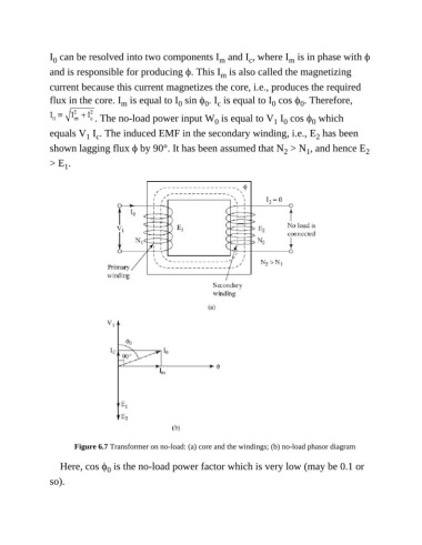
                       Figure 6.7 Transformer on no-load: (a) core and the windings; (b) no-load phasor diagram

                  Here, cos ϕ  is the no-load power factor which is very low (may be 0.1 or
                                0
               so).
   539   540   541   542   543   544   545   546   547   548   549