Page 547 - Basic Electrical Engineering
P. 547

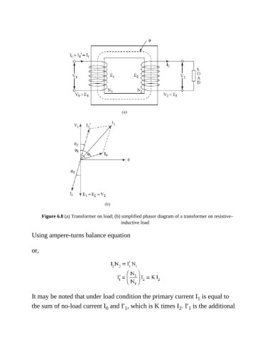
Figure 6.8 (a) Transformer on load; (b) simplified phasor diagram of a transformer on resistive–
                                                        inductive load

               Using ampere-turns balance equation


               or,


               It may be noted that under load condition the primary current I  is equal to
                                                                                           1
               the sum of no-load current I  and I′ , which is K times I . I′  is the additional
                                                                                      1
                                                                                  2
                                                 0
                                                          1
   542   543   544   545   546   547   548   549   550   551   552