
Page 551 - Basic Electrical Engineering
P. 551
drawn by the transformer. So, the circuit shown in Fig. 6.11 is an
approximate equivalent circuit of the transformer.
The primary circuit impedance is Z and the secondary winding impedance
1
is Z .
2
Note that the transformer is a coupled circuit. For the sake of simplicity in
calculation, we might like to convert it into a single circuit by transferring the
circuit parameters of the primary circuit to the secondary circuit and vice
versa.
Let us see how the secondary circuit parameters can be transferred to the
primary side. Let R′ be the value of R when transferred to the primary side.
2
2
By considering the same amount of losses in the resistance when transferred
from one current level to the other, we can equate the copper losses as
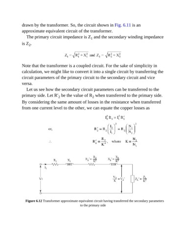
Figure 6.12 Transformer approximate equivalent circuit having transferred the secondary parameters
to the primary side