
Page 548 - Basic Electrical Engineering
P. 548
current drawn by the primary winding due to the loading of the transformer.
Thus,
I = I + I′ = I + KI 2
1
0
1
0
The phasor diagram relating all the parameters under loading condition
neglecting the voltage drop due to winding resistances and leakage reactances
has been shown in Fig. 6.8 (b). The phasor diagram is for some resistive–
inductive load when the load power factor angle is ϕ. That is why I has been
2
shown lagging the load voltage V by an angle ϕ . I′ is the additional
2
2
1
primary current drawn from the supply source to counter balance the
magnetizing effect of I (I N = I′ N ).
1 1
2 2 2
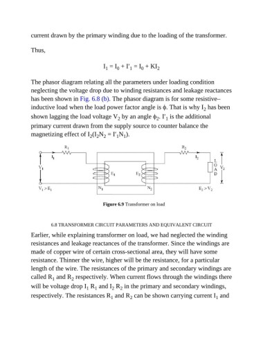
Figure 6.9 Transformer on load
6.8 TRANSFORMER CIRCUIT PARAMETERS AND EQUIVALENT CIRCUIT
Earlier, while explaining transformer on load, we had neglected the winding
resistances and leakage reactances of the transformer. Since the windings are
made of copper wire of certain cross-sectional area, they will have some
resistance. Thinner the wire, higher will be the resistance, for a particular
length of the wire. The resistances of the primary and secondary windings are
called R and R respectively. When current flows through the windings there
2
1
will be voltage drop I R and I R in the primary and secondary windings,
1
2
1
2
respectively. The resistances R and R can be shown carrying current I and
1
1
2