
Page 550 - Basic Electrical Engineering
P. 550
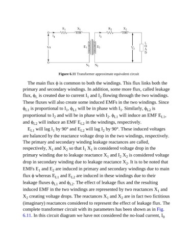
Figure 6.11 Transformer approximate equivalent circuit

                  The main flux ϕ is common to both the windings. This flux links both the

               primary and secondary windings. In addition, some more flux, called leakage
               flux, ϕ  is created due to current I  and I  flowing through the two windings.
                                                                2
                       L
                                                        1
               These fluxes will also create some induced EMFs in the two windings. Since
               ϕ  is proportional to I , ϕ  will be in phase with I . Similarly, ϕ  is
                                                                                              L2
                                                                             1
                 L1
                                           1
                                               L1
               proportional to I  and will be in phase with I . ϕ  will induce an EMF E ,
                                                                         L1
                                   2
                                                                     2
                                                                                                       L1
               and ϕ  will induce an EMF E  in the windings, respectively.
                      L2
                                                    L2
                  E  will lag I  by 90° and E  will lag I  by 90°. These induced voltages
                                                                  2
                                                    L2
                                  1
                    L1
               are balanced by the reactance voltage drop in the two windings, respectively.
               The primary and secondary winding leakage reactances are called,
               respectively, X  and X  so that I  X  is considered voltage drop in the
                                  1
                                           2
                                                      1
                                                          1
               primary winding due to leakage reactance X  and I  X  is considered voltage
                                                                                 2
                                                                            2
                                                                     1
               drop in secondary winding due to leakage reactance X . It is to be noted that
                                                                                 2
               EMFs E  and E  are induced in primary and secondary windings due to main
                                  2
                         1
               flux ϕ whereas E  and E  are induced in these windings due to their
                                              L2
                                    L1
               leakage fluxes ϕ  and ϕ . The effect of leakage flux and the resulting
                                   L1
                                             L2
               induced EMF in the two windings are represented by two reactances X  and
                                                                                                    1
               X  creating voltage drops. The reactances X  and X  are in fact two fictitious
                                                                              2
                  2
                                                                    1
               (imaginary) reactances considered to represent the effect of leakage flux. The
               complete transformer circuit with its parameters has been shown as in Fig.
               6.11. In this circuit diagram we have not considered the no-load current, I              0