
Page 555 - Basic Electrical Engineering
P. 555
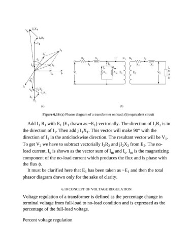
Figure 6.16 (a) Phasor diagram of a transformer on load; (b) equivalent circuit

                  Add I  R  with E  (E  drawn as −E ) vectorially. The direction of I R  is in
                                       1
                                            1
                         1
                             1
                                                             1
                                                                                                   1 1
               the direction of I . Then add j I X . This vector will make 90° with the
                                                     1 1
                                   1
               direction of I  in the anticlockwise direction. The resultant vector will be V .
                               1
                                                                                                          1
               To get V  we have to subtract vectorially I R  and jI X  from E . The no-
                                                                                            2
                                                                  2 2
                                                                              2 2
                          2
               load current, I  is shown as the vector sum of I  and I . I  is the magnetizing
                                                                                c
                                                                       m
                                                                                   m
                                o
               component of the no-load current which produces the flux and is phase with
               the flux ϕ.
                  It must be clarified here that E  has been taken as −E  and then the total
                                                                                  1
                                                       1
               phasor diagram drawn only for the sake of clarity.
                                        6.10 CONCEPT OF VOLTAGE REGULATION
               Voltage regulation of a transformer is defined as the percentage change in
               terminal voltage from full-load to no-load condition and is expressed as the
               percentage of the full-load voltage.


               Percent voltage regulation