
Page 553 - Basic Electrical Engineering
P. 553
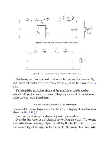
Figure 6.13 Exact equivalent circuit of a transformer


                                    Figure 6.14 Approximate equivalent circuit of a transformer


                  Combining the resistances and reactances, the equivalent resistances R′               e
               and equivalent reactance X′  are represented as Z′  as has been shown in Fig.
                                                                           e
                                                 e
               6.15.

                  This simplified equivalent circuit of the transformer can be used to
               calculate the performance in terms of voltage regulation of the transformer
               under various loading conditions.


                                       6.9 PHASOR DIAGRAM OF A TRANSFORMER

               The complete phasor diagram of a transformer at a lagging Pf load has been

               shown in Fig. 6.16 (a).
                  Procedure for drawing the phasor diagram is given below.

                  Draw the flux vector as the reference vector along the x-axis. The voltage
               induced in the two windings, E  ans E  will lag flux by 90°. If it is a step-up
                                                     1
                                                             2
               transformer, E  will be bigger in length than E . Otherwise, they can also be
                                 2
                                                                       1