
Page 549 - Basic Electrical Engineering
P. 549
I as in Fig. 6.9. When the resistances have been shown separately, the
2
windings are considered made up of some number of turns but without
having any resistances. In other words, we may say that when the resistances
of the windings have been shown separately, the windings will be assumed as
having no resistance. It may be noted that input voltage V is higher than the
1
induced EMF E (current flows from higher potential V to lower potential
1
1
E ). The induced EMF E is greater than load terminal voltage V .
1
2
2
Neglecting reactances of the windings, the voltage equation are
V − I R = E 1
1
1
1
and
E − I R = V 2
2
2
2
The power loss in the primary and secondary windings are respectively, R 1
and R These are also called copper losses. Note that the above two voltage
2
equations have been written considering only the resistances of the windings.
Voltage drop due to reactances of the windings has been neglected.
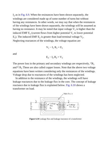
In addition to the resistance of the windings, the windings will have
leakage reactances due to the leakage flux in the core. The concept of leakage
reactance due to leakage flux is explained below. Fig. 6.10 shows a
transformer on load.
Figure 6.10 Leakage flux and leakage reactance of a transformer