
Page 562 - Basic Electrical Engineering
P. 562
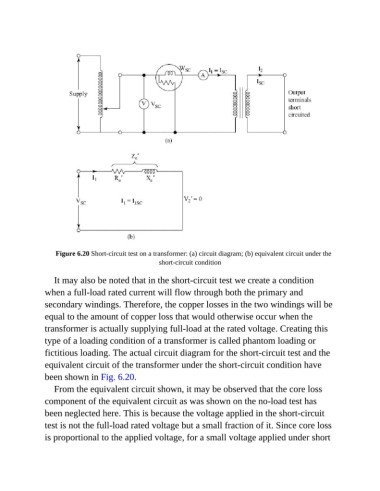
Figure 6.20 Short-circuit test on a transformer: (a) circuit diagram; (b) equivalent circuit under the
                                                    short-circuit condition


                  It may also be noted that in the short-circuit test we create a condition
               when a full-load rated current will flow through both the primary and

               secondary windings. Therefore, the copper losses in the two windings will be
               equal to the amount of copper loss that would otherwise occur when the

               transformer is actually supplying full-load at the rated voltage. Creating this
               type of a loading condition of a transformer is called phantom loading or
               fictitious loading. The actual circuit diagram for the short-circuit test and the

               equivalent circuit of the transformer under the short-circuit condition have
               been shown in Fig. 6.20.

                  From the equivalent circuit shown, it may be observed that the core loss
               component of the equivalent circuit as was shown on the no-load test has

               been neglected here. This is because the voltage applied in the short-circuit
               test is not the full-load rated voltage but a small fraction of it. Since core loss

               is proportional to the applied voltage, for a small voltage applied under short