


Page 971 - Basic Electrical Engineering
P. 971
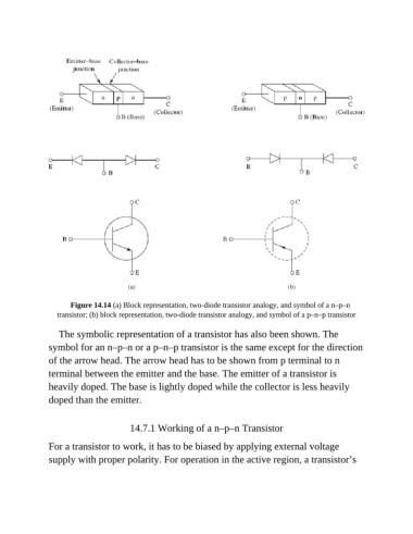
Figure 14.14 (a) Block representation, two-diode transistor analogy, and symbol of a n–p–n
                  transistor; (b) block representation, two-diode transistor analogy, and symbol of a p–n–p transistor

                  The symbolic representation of a transistor has also been shown. The

               symbol for an n–p–n or a p–n–p transistor is the same except for the direction
               of the arrow head. The arrow head has to be shown from p terminal to n
               terminal between the emitter and the base. The emitter of a transistor is

               heavily doped. The base is lightly doped while the collector is less heavily
               doped than the emitter.


                                        14.7.1 Working of a n–p–n Transistor

               For a transistor to work, it has to be biased by applying external voltage
               supply with proper polarity. For operation in the active region, a transistor’s

