
Page 159 - Fiber Optic Communications Fund
P. 159
140 Fiber Optic Communications
1 1 0 1 1 1 0 0 0 1
A
Voltage
Unipolar
0
1 2 3 4 5 6 7 8 9 10
(a) Time (Arb. units)
A
Polar Voltage
Time
–A
(b)
A
Bipolar Voltage Time
–A
(c)
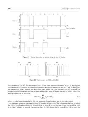
Figure 4.1 Various line codes: (a) unipolar, (b) polar, and (c) bipolar.
x(t) NRZ x(t) RZ
1 1 0 1 1 1 1 1 0 1 1 1
t t
(a) (b)
Figure 4.2 Pulse shapes: (a) NRZ, and (b) RZ.
slot, as shown in Fig. 4.2. The advantage of NRZ is that fewer transitions between ‘0’ and ‘1’ are required
compared with RZ, since the signal amplitude remains the same if consecutive bits are ‘1’ or ‘0’. Therefore,
the bandwidth of a NRZ signal is less than that of a RZ signal. The wider spectral width of a RZ signal can
also be understood from the fact that the pulse width of RZ pulse is shorter than that of a NRZ pulse. The
message signal may be written as
∞
∑
m(t)= A 0 a p(t − nT ), (4.1)
b
n
n=−∞
where a is the binary data in the bit slot, p(t) represents the pulse shape, and A is a real constant.
n 0
An important parameter that characterizes a RZ signal is the duty cycle. This is defined as the time for which
the light is turned on in a bit interval divided by the bit interval, i.e., the fraction of time over which the light
is on “duty” within a bit interval. For example, for a 10-Gb/s system, the bit interval T is 100 ps and if the
b