
Page 162 - Fiber Optic Communications Fund
P. 162
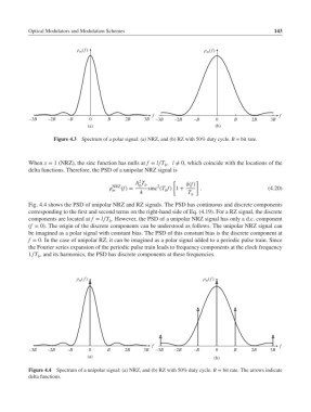
Optical Modulators and Modulation Schemes                                          143


                           ρ m ( f)                                   ρ m ( f)


                                                     f                                          f
           –3B   –2B    –B     0      B    2B     3B  –3B   –2B    –B     0     B     2B     3B
                               (a)                                        (b)

                   Figure 4.3  Spectrum of a polar signal: (a) NRZ, and (b) RZ with 50% duty cycle. B = bit rate.


           When x = 1 (NRZ), the sinc function has nulls at f = l∕T , l ≠ 0, which coincide with the locations of the
                                                         b
           delta functions. Therefore, the PSD of a unipolar NRZ signal is
                                                2
                                               A T          [      ]
                                       NRZ      0 b   2         (f)
                                        (f)=     sinc (T f) 1 +    .                      (4.20)
                                       m                 b
                                                4                T
                                                                  b
           Fig. 4.4 shows the PSD of unipolar NRZ and RZ signals. The PSD has continuous and discrete components
           corresponding to the first and second terms on the right-hand side of Eq. (4.19). For a RZ signal, the discrete
           components are located at f = l∕T . However, the PSD of a unipolar NRZ signal has only a d.c. component
                                      b
           (f = 0). The origin of the discrete components can be understood as follows. The unipolar NRZ signal can
           be imagined as a polar signal with constant bias. The PSD of this constant bias is the discrete component at
           f = 0. In the case of unipolar RZ, it can be imagined as a polar signal added to a periodic pulse train. Since
           the Fourier series expansion of the periodic pulse train leads to frequency components at the clock frequency
           1∕T , and its harmonics, the PSD has discrete components at these frequencies.
              b


                           ρ ( f)                                     ρ ( f)
                                                                       m
                            m


                                                     f                                          f
           –3B   –2B    –B     0     B     2B     3B  –3B   –2B    –B     0     B     2B     3B
                               (a)                                        (b)

           Figure 4.4 Spectrum of a unipolar signal: (a) NRZ, and (b) RZ with 50% duty cycle. B = bit rate. The arrows indicate
           delta functions.