
Page 247 - Fiber Optic Communications Fund
P. 247
228 Fiber Optic Communications
mode dispersion (PMD) in an electrical domain. In the case of coherent detection, the detection process is
linear–the complex optical field envelope is linearly translated into an electrical domain and, therefore, the
inverse fiber transfer function can be realized using DSP to compensate for dispersion and PMD. (ii) With
coherent detection, higher spectral efficiencies can be realized using multi-level modulation formats that make
use of both amplitude and phase modulation.
5.6.1 Single-Branch Coherent Receiver
In this section, we assume that the polarization of the received signal is perfectly aligned with that of the local
oscillator (LO), and we use scalar notation. The polarization effects are considered in Section 5.6.5. Let the
transmitted signal be
q (t)= A s(t) exp (−i t), (5.85)
T
c
T
2
where s(t) is the complex field envelope, is the frequency of the optical carrier, and A is the peak trans-
c T
mitter power. Let us assume a perfect optical channel that introduces neither distortion nor noise. However,
the phase of the optical carrier changes due to propagation, and the field amplitude may be attenuated. Let
the received signal be
q (t)= A s(t) exp [−i( t + )] (5.86)
r r c c
and the local oscillator output be
q (t)= A exp [−i( t + )], (5.87)
LO LO LO LO
where A 2 = P LO is the LO power, and LO is the phase. These two signals are combined using a 3-dB
LO
1
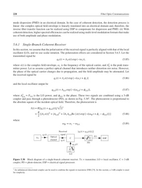
coupler and pass through a photodetector (PD), as shown in Fig. 5.30 . The photocurrent is proportional to
the absolute square of the incident optical field. Therefore, the photocurrent is
√
I(t)= R|[q (t)+ q 2
r LO (t)]∕ 2|
R 2 2
= {|A s(t)| + |A LO | + 2A A Re {s(t) exp [−i( t + − LO )]}} (5.88)
IF
r LO
c
r
2
where
= − LO (5.89)
IF
c
Received [q (t) + q (t)]/ 2
r
LO
q (t) signal
T
Tx Optical C I(t) ESP
channel q (t)
r
PD
q (t)
LO
LO
Figure 5.30 Block diagram of a single-branch coherent receiver. Tx = transmitter, LO = local oscillator, C = 3-dB
coupler, PD = photo-detector, ESP = electrical signal processor.
1 An unbalanced directional coupler can be used to combine the signals to maximize SNR [74]. In this section, a 3-dB coupler is used
for simplicity.