
Page 250 - Fiber Optic Communications Fund
P. 250
Optical Receivers 231
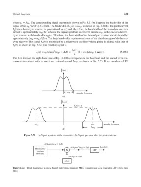
where I = RP . The corresponding signal spectrum is shown in Fig. 5.31(b). Suppose the bandwidth of the
0
0
signal s(t) is ∕2 (Fig. 5.31(a)). The bandwidth of I (t) is 2 , as shown in Fig. 5.31(b). The photocurrent
B
d
B
I (t) in a homodyne receiver is proportional to s(t) and, therefore, the bandwidth of the homodyne receiver
d
circuit is approximately ∕2, whereas the signal spectrum is centered around in the case of a hetero-
B
IF
dyne receiver with bandwidth ∕. Therefore, the bandwidth of the heterodyne receiver circuit should be
B
approximately ( + )∕(2). The large bandwidth requirement is one of the disadvantages of the hetero-
B
IF
dyne receiver. The signal I (t) is multiplied by a microwave oscillator whose phase is aligned with that of
d
I (t), as shown in Fig. 5.32. The resulting signal is
d
I s(t)
0
2
I (t)= I s(t)cos ( t +Δ)= {1 + cos [2( +Δ)]}. (5.100)
1 0 IF IF
2
The first term on the right-hand side of Eq. (5.100) corresponds to the baseband and the second term cor-
responds to a signal with its spectrum centered around 2 , as shown in Fig. 5.33. If we introduce a LPF
IF
˜ s (ω)
ω B Angular frequency
(a)
˜
I d (ω)
I 0 s (ω)/ 2
˜
Angular frequency
–ω IF ω IF
2ω B
(b)
Figure 5.31 (a) Signal spectrum at the transmitter. (b) Signal spectrum after the photo-detector.
s(t)I cos(ω IF t + ∆ϕ)
0
2
s(t)I cos (ω IF t + ∆ϕ) I 0 s(t) / 2
Heterodyne X 0 LPF
receiver
front end
cos(ω IF t + ∆ϕ)
MLO
Figure 5.32 Block diagram of a single-branch heterodyne receiver. MLO = microwave local oscillator, LPF = low-pass
filter.