
Page 255 - Fiber Optic Communications Fund
P. 255
236 Fiber Optic Communications
∘
Note that i = e i∕2 corresponding to a 90 phase shift as shown in Fig. 5.36. The corresponding photocurrent
is
I (t)= R|q 2 (5.118)
Q out,Q |
RA A
r LO
≈ Im{s(t) exp [−i( t +Δ)]}
IF
2
RA A
r LO
≈ |s(t)| sin ( t + (t)+Δ). (5.119)
IF
s
2
To obtain Eq. (5.118), we have used the formula
∗
2iIm{X}=(X − X ). (5.120)
For a homodyne receiver, = 0 and when the phase mismatch Δ = 0, we have
IF
RA A
r LO
I (t)= Re [s(t)], (5.121)
I
2
RA A
r LO
I (t)= Im [s(t)]. (5.122)
Q
2
The electrical signal processing unit forms the complex current I(t)= I (t)+ iI (t)= RA A s(t)∕2. Thus, the
I Q r LO
transmitted complex signal could be retrieved. In Fig. 5.36, the components inside the rectangle constitute a
∘
2 × 290 optical hybrid. It is a device with two inputs and two outputs, as shown in Fig. 5.37. The transfer
∘
matrix of an ideal 2 × 290 hybrid can be written as
[ ]
1 11
T = . (5.123)
2 1 i
∘
Let the input of the 2 × 290 hybrid be
[ ]
q (t)
r
q = , (5.124)
in
q LO (t)
where q (t) and q LO (t) are the complex fields of received signal and local oscillator, respectively, as shown in
r
∘
Fig. 5.37. Let the outputs of the 2 × 290 hybrid be
[ ]
q
q = out,I . (5.125)
out q
out,Q
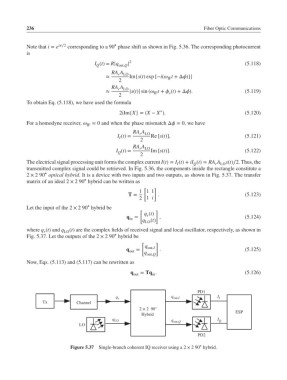
Now, Eqs. (5.113) and (5.117) can be rewritten as
q out = Tq . (5.126)
in
PD1
q r q out,I I I
Tx Channel
2 × 2 90°
ESP
Hybrid
q LO q I Q
LO out,Q
PD2
∘
Figure 5.37 Single-branch coherent IQ receiver using a 2 × 290 hybrid.