Page 252 - Fiber Optic Communications Fund
P. 252

Optical Receivers                                                                  233


                             As(t)exp[–i(ω c t + ϕ )]            PD1
                                          c
                                                                      I +     I = I – I
                  Tx           Optical             DC                            +   –
                              channel                                     +
                                                                             Σ         ESP
                                                                          –
                                                                      I –
                                        A LO exp[–i(ω t + ϕ )]   PD2
                                                LO
                                                     LO


                                     LO

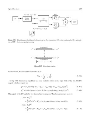
           Figure 5.34  Block diagram of a balanced coherent receiver. Tx = transmitter, DC = directional coupler, PD = photode-
           tector, ESP = electronic signal processing.


                                                Waveguide 1
                                     q 1 in  In 1             Out 1   q 1 out

                                                    d

                                     q 2 in  In 2             Out 2   q 2 out
                                                Waveguide 2
                                                    L

                                         Figure 5.35  Directional coupler.


           In other words, the transfer function of the DC is
                                                      [     ]
                                                    1   1 −i
                                             T               .                             (5.106)
                                              DC  = √  −i 1
                                                     2
            In Fig. 5.34, the received signal field and local oscillator output are the input fields of the DC. The DC
           outputs with these inputs are
                                                                             √
                          q out  ={A s(t) exp [−i( t +  )] − iA  exp [−i(  t +   )]}∕ 2,  (5.107)
                           1     r          c    c     LO         LO    LO
                                                                              √
                          q out  ={−iA s(t) exp [−i( t +  )] + A  exp [−i(  t +   )]}∕ 2.  (5.108)
                           2       r          c    c     LO        LO    LO
           The outputs of the DC are fed to two identical photo-detectors. The photocurrents are given by

                                   out 2
                           I (t)= R|q |
                           +       1
                                 R  2    2   2
                               =  {A |s(t)| + A  − 2A A  Im{s(t) exp [−i( t +Δ)]}},    (5.109)
                                                                      IF
                                    r
                                                    r LO
                                 2           LO
                                   out 2
                           −
                           I (t)= R|q |
                                   2
                                 R  2    2   2
                               =  {A |s(t)| + A  + 2A A  Im{s(t) exp [−i( t +Δ)]}}.    (5.110)
                                    r
                                                    r LO
                                                                      IF
                                 2           LO
   247   248   249   250   251   252   253   254   255   256   257