
Page 254 - Fiber Optic Communications Fund
P. 254
Optical Receivers 235
C PD1
Received signal q r (t)/ 2 q out, I (t) I I
q r (t)
PS
q LO (t)/ 2
q LO (t)
LO PS
ESP
q (t)/ 2
LO
π
2 Phase-shifter
q (t)/ 2 q out,Q (t)
r
I Q
C
PD2
o
2×2 90 hybrid
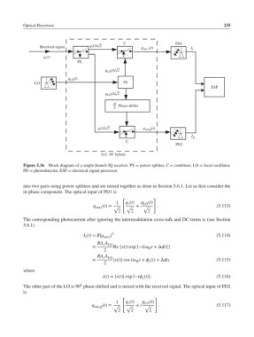
Figure 5.36 Block diagram of a single-branch IQ receiver. PS = power splitter, C = combiner, LO = local oscillator,
PD = photodetector, ESP = electrical signal processor.
into two parts using power splitters and are mixed together as done in Section 5.6.1. Let us first consider the
in-phase component. The optical input of PD1 is
[ ]
1 q (t) q LO (t)
r
q out,I (t)= √ √ + √ . (5.113)
2 2 2
The corresponding photocurrent after ignoring the intermodulation cross-talk and DC terms is (see Section
5.6.1)
I (t)= R|q out,I | 2 (5.114)
I
RA A
r LO
≈ Re {s(t) exp [−i( t +Δ)]}
IF
2
RA A
r LO
≈ |s(t)| cos ( t + (t)+Δ), (5.115)
IF
s
2
where
s(t)= |s(t)| exp [−i (t)]. (5.116)
s
∘
The other part of the LO is 90 phase-shifted and is mixed with the received signal. The optical input of PD2
is
[ ]
1 q (t) q LO (t)
r
q . (5.117)
out,Q (t)= √ √ + i √
2 2 2