
Page 350 - Fiber Optic Communications Fund
P. 350
Transmission System Design 331
Using a Nyquist filter,
1
B = . (7.172)
e
2T b
Eq. (7.171) becomes
√
2P T
1r b
Q PSK = . (7.173)
P ASE b
T + hf∕2
Using Eqs. (7.164) and (7.165), Eq. (7.173) becomes
2N s
2
Q = . (7.174)
PSK N + 1∕2
n
Example 7.9
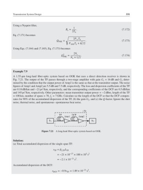
A 1.55-μm long-haul fiber-optic system based on OOK that uses a direct detection receiver is shown in
Fig. 7.21. The output of the TF passes through a two-stage amplifier with gain G = 16 dB and G deter-
2
1
mined by the condition that the output power of Amp2 is the same as that at the transmitter output. The noise
figures of Amp1 and Amp2 are 5.5 dB and 7.5 dB, respectively. The loss and dispersion coefficients of the TF
2
are 0.18 dB/km and −21 ps /km, respectively, and the corresponding coefficients of the DCF are 0.5 dB/km
2
and 145 ps /km, respectively. Other parameters: mean transmitter output power =−2 dBm, length of the TF
= 100 km, number of spans = 70, f = 7 GHz. Calculate (a) the length of the DCF so that the DCF compen-
e
sates for 90% of the accumulated dispersion of the TF, (b) the gain G , and (c) the Q-factor. Ignore the shot
2
noise, thermal noise, and spontaneous–spontaneous beat noise.
Figure 7.21 A long-haul fiber-optic system based on OOK.
Solution:
(a) Total accumulated dispersion of the single-span TF:
s TF = 2,TF TF
L
3 2
=−21 × 10 −27 × 100 × 10 s
=−2.1 × 10 −21 2
s .
Accumulated dispersion of the DCF:
s ,
s DCF =−0.9s TF = 1.89 × 10 −21 2