Page 355 - Fiber Optic Communications Fund
P. 355

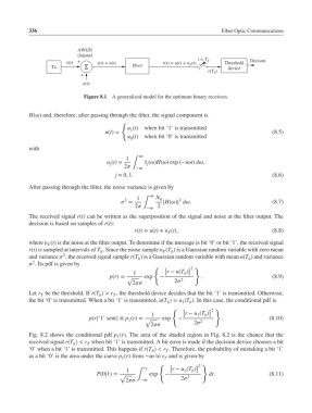
336                                                               Fiber Optic Communications


                             AWGN
                             channel
                         x(t)  +    x(t) + n(t)           r(t) = u(t) + n F (t)  t = T b  Threshold    Decison
                    Tx         ∑               H(ω)                             device
                                                                         r(T b )
                              +
                               n(t)

                               Figure 8.1  A generalized model for the optimum binary receivers.


            H() and, therefore, after passing through the filter, the signal component is
                                            {
                                              u (t) when bit ‘1’ is transmitted
                                               1
                                      u(t)=                                                    (8.5)
                                              u (t) when bit ‘0’ is transmitted
                                               0
            with
                                                  ∞
                                             1
                                       u (t)=       ̃ x ()H() exp (−it) d,
                                        j    2 ∫  j
                                                 −∞
                                          j = 0, 1.                                            (8.6)
            After passing through the filter, the noise variance is given by
                                                     ∞
                                                 1     N 0     2
                                             2
                                             =          |H()| d.                         (8.7)
                                                2 ∫ −∞  2
            The received signal r(t) can be written as the superposition of the signal and noise at the filter output. The
            decision is based on samples of r(t):
                                                r(t)= u(t)+ n (t),                             (8.8)
                                                           F
            where n (t) is the noise at the filter output. To determine if the message is bit ‘0’ or bit ‘1’, the received signal
                   F
            r(t) is sampled at intervals of T . Since the noise sample n (T ) is a Gaussian random variable with zero mean
                                     b                    F  b
                        2
            and variance  , the received signal sample r(T ) is a Gaussian random variable with mean u(T ) and variance
                                                 b                                     b
              2
             . Its pdf is given by
                                                                  ] }
                                                                   2
                                                       { [
                                                1          r − u(T )
                                                                 b
                                        p(r)= √    exp   −      2      .                       (8.9)
                                               2          2
            Let r be the threshold. If r(T ) > r , the threshold device decides that the bit ‘1’ is transmitted. Otherwise,
                T
                                         T
                                    b
            the bit ‘0’ is transmitted. When a bit ‘1’ is transmitted, u(T )= u (T ). In this case, the conditional pdf is
                                                                1
                                                           b
                                                                   b
                                                             { [         ] }
                                                                          2
                                                      1          r − u (T )
                                                                     1
                                                                        b
                                              1
                                 p(r|‘1’ sent) ≡ p (r)= √  exp  −     2       .               (8.10)
                                                      2         2
            Fig. 8.2 shows the conditional pdf p (r). The area of the shaded region in Fig. 8.2 is the chance that the
                                          1
            received signal r(T ) < r when bit ‘1’ is transmitted. A bit error is made if the decision device chooses a bit
                           b    T
            ‘0’ when a bit ‘1’ is transmitted. This happens if r(T ) < r . Therefore, the probability of mistaking a bit ‘1’
                                                      b
                                                           T
            as a bit ‘0’ is the area under the curve p (r) from −∞ to r and is given by
                                            1
                                                          T
                                                                      2
                                                        { [          ] }
                                             1     r T       r − u (T )
                                                                 1
                                                                    b
                                   P(0|1)= √     ∫   exp  −       2      dr.                  (8.11)
                                             2  −∞          2
   350   351   352   353   354   355   356   357   358   359   360