
Page 410 - Fiber Optic Communications Fund
P. 410
Channel Multiplexing Techniques 391
[ ̃ ̃ ]
M () M ()
xx
xy
̃
M = , (9.10)
̃
̃
M () M ()
yx yy
[ ]
̃ m ()
x
̃ m = . (9.11)
̃ m ()
y
̃ −1
Multiplying Eq. (9.8) by M on both sides, we find
̃ −1 ̃
̃ m = M I. (9.12)
̃ −1
The digital signal processing of the coherent receiver can be used to compute M (see Chapter 11) and, thus,
the message signal vector ̃ m can be retrieved.
9.3 Wavelength-Division Multiplexing
In a WDM system, multiple optical carriers of different wavelengths are modulated by independent elec-
trical data. Since wavelength and frequency f are related by = c∕f, WDM may also be considered as
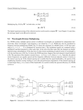
frequency-division multiplexing (FDM). Fig. 9.3 shows the schematic of a WDM system. A CW laser oper-
ating at , j = 1, 2, … , N is modulated by electrical data j. The modulated signals are combined using a
j
multiplexer and then launched to a fiber-optic link. At the end of the fiber-optic link, the channels are demul-
tiplexed using a demultiplexer. If the data rate of a data stream modulating an optical carrier of wavelength j
is B, the total data rate is NB. Fig. 9.4 shows the WDM spectrum. Suppose that each channel is band-limited to
f Hz. The spectrum of the channel j extends from f − f ∕2to f + f ∕2, where f = c∕ . Typically, the optical
j
s
j
s
j
j
s
carrier frequencies are equally spaced and the frequency difference between adjacent carriers is known as
the channel spacing Δf. If the channel spacing Δf is smaller than the signal bandwidth f , the spectra of the
s
neighboring channels overlap, leading to cross-talk and performance degradation. If the channel spacing Δf
is much larger than f , it is a waste of fiber bandwidth. It is useful to define the spectral efficiency of a WDM
s
system as
B
= , (9.13)
Δf
Data 1
Laser 1 1
Mod 1
1
Rx 1
Data 2
Laser 2 2 2
DEMUX
Mod 1 Rx 2
MUX
N
Data N Fiber-optic link Rx N
Laser N N
Mod 1
Figure 9.3 Schematic of a WDM system: Mod = modulator, MUX = multiplexer, DEMUX = demultiplexer.