Page 414 - Fiber Optic Communications Fund
P. 414

Channel Multiplexing Techniques                                                    395


                                       White light
                                  1  +  2  + ... +  N
                                                                     1
                                                                       2

                                                                        N * 1

                                                                        N

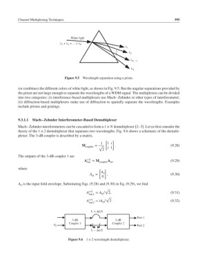
                                    Figure 9.5 Wavelength separation using a prism.

           (or combines) the different colors of white light, as shown in Fig. 9.5. But the angular separations provided by
           the prism are not large enough to separate the wavelengths of a WDM signal. The multiplexers can be divided
           into two categories: (i) interference-based multiplexers use Mach–Zehnder or other types of interferometer;
           (ii) diffraction-based multiplexers make use of diffraction to spatially separate the wavelengths. Examples
           include prisms and gratings.


           9.3.1.1  Mach–Zehnder Interferometer-Based Demultiplexer

           Mach–Zehnder interferometers can be cascaded to form a 1 × N demultiplexer [2–5]. Let us first consider the
           theory of the 1 × 2 demultiplexer that separates two wavelengths. Fig. 9.6 shows a schematic of the demulti-
           plexer. The 3-dB coupler is described by a matrix,
                                                         [   ]
                                                       1  1 i
                                             M coupler  = √   .                             (9.28)
                                                       2  i 1
           The outputs of the 3-dB coupler 1 are
                                              A co1  = M coupler A ,                        (9.29)
                                               out
                                                            in
           where                                      [  ]
                                                       A 0
                                                 A =   0  ,                                 (9.30)
                                                  in
           A is the input field envelope. Substituting Eqs. (9.28) and (9.30) in Eq. (9.29), we find
            0
                                                         √
                                               A co1  = A ∕ 2,                              (9.31)
                                                out,1  0
                                                         √
                                               A co1  = iA ∕ 2                              (9.32)
                                                out,2   0
                                                  L + ΔL/2
                                                                          Port 1
                                       3-dB                   3-dB
                                      Coupler 1              Coupler 2
                              A 0                                         Port 2
                                                  L * ΔL/2

                                     Figure 9.6  1 × 2 wavelength demultiplexer.
   409   410   411   412   413   414   415   416   417   418   419