
Page 417 - Fiber Optic Communications Fund
P. 417
398 Fiber Optic Communications
, and , equally spaced in frequency. Let the frequency spacing be Δf. The path-length difference ΔL of
3
4
Demux 1 is chosen so that odd and even wavelengths are directed to ports 1 and 2 of Demux 1, respectively.
The frequency difference between channels 1 and 3 is 2Δf.If ΔL is chosen using Eq. (9.48), channels 1 and 2
are directed to ports 1 and 2 of Demux 1, respectively. Since the power transmittance is periodic with period
2Δf (see Fig. 9.7), channels 1 and 3 have the maximum power transmittance at port 1 of Demux 1. Channels
1 and 3 are separated using Demux 2. Since the frequency difference between channels 1 and 3 is 2Δf, ΔL
of Demux 2 should be half that of Demux 1. In this analysis, we assume that the couplers are ideal 3-dB
couplers and the MZ interferometer arms have no losses. As a result, we find that when the power output at
port 1 is maximum that at port 2 is zero, and vice versa (see Fig. 9.7). This corresponds to zero cross-talk
between channels. In practice, the power-coupling ratio deviates from 3 dB and the loss due to propagation
in MZ cannot be ignored. When these effects are included, it is found that the power output at port 2 is not
zero while that at port 1 is maximum, which leads to cross-talk between channels [5]. A 10 GHz-spaced
silica-based integrated-optic 8-channel MZ multi/demultiplexer is fabricated with a cross-talk of −10 dB
or less [5].
9.3.1.2 Diffraction-Based Multiplexer/Demultiplexers
Diffraction-based multi/demultiplexers make use of Bragg diffraction to isolate/combine the wavelength
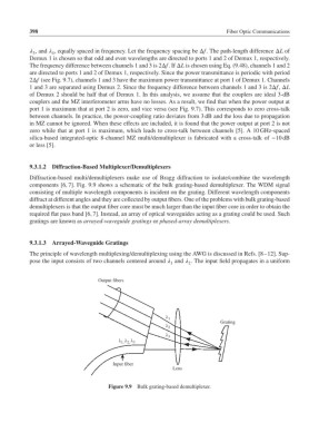
components [6, 7]. Fig. 9.9 shows a schematic of the bulk grating-based demultiplexer. The WDM signal
consisting of multiple wavelength components is incident on the grating. Different wavelength components
diffract at different angles and they are collected by output fibers. One of the problems with bulk grating-based
demultiplexers is that the output fiber core must be much larger than the input fiber core in order to obtain the
required flat pass band [6, 7]. Instead, an array of optical waveguides acting as a grating could be used. Such
gratings are known as arrayed-waveguide gratings or phased-array demultiplexers.
9.3.1.3 Arrayed-Waveguide Gratings
The principle of wavelength multiplexing/demultiplexing using the AWG is discussed in Refs. [8–12]. Sup-
pose the input consists of two channels centered around and . The input field propagates in a uniform
1 2
Output fibers
1
Grating
2
3
1, 2, 3
Input fiber
Lens
Figure 9.9 Bulk grating-based demultiplexer.