
Page 418 - Fiber Optic Communications Fund
P. 418
Channel Multiplexing Techniques 399
Input 2
1
0
*1
1, 2
*2
Arrayed waveguides
Output waveguide 1
1
2
Output waveguide 2
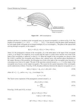
Figure 9.10 AWG demultiplexer.
medium and then it is incident on the waveguide array (or arrayed waveguides), as shown in Fig. 9.10. The
lengths of waveguides l , j =−N∕2, … , −1, 0, 1, … , N∕2 − 1 are chosen so that the phase shifts introduced
j
by each single-mode waveguide are an integral multiple of 2 at wavelength . The phase of the optical field
1
arriving through waveguide j at the output is
( )= ( )l + ( )= 2m + ( ), (9.49)
j 1 1 j j 1 j j 1
where is the propagation constant of the waveguide j, is the initial phase at the input of the waveguide
j
j and m is an integer. For simplicity, let us assume that the input is a point source and the wave front at the
j
input of the waveguides is spherical, so that = . When the lengths of the waveguides are chosen so that
j
Eq. (9.49) is satisfied, the waveguide array behaves like a phased array with uniform phase distribution at
the output. Because of the geometry, the diverging wave front at the input of the waveguide array becomes a
converging wave front at its output. The part of the spectrum centered around , j = 1, 2 at the output of the
j
waveguide array focuses on the output waveguide j. The reason for the spatial separation of the wavelengths
can be understood as follows. From Eq. (9.49), the phase difference between the adjacent waveguides at is
1
( ) ≡ ( )− j−1 ( )= ( )Δl = 2m, (9.50)
1
1
1
j
1
where Δl = l − l and m = m − m is an integer. Let
j j−1 j j−1
= +Δ. (9.51)
2
1
The Taylor-series expansion of the propagation constant around is
1
( )≅ ( )+ kΔ, (9.52)
2 1
d |
k = | . (9.53)
|
d |= 1
From Eqs. (9.49) and (9.52), we have
( )= ( )l + ( )
2
2
2 j
j
= ( )+Δ + kΔl , (9.54)
j
1
j
where
Δ = ( )− ( )= ( )− ( ). (9.55)
1
2
j
2
1
j