
Page 423 - Fiber Optic Communications Fund
P. 423
404 Fiber Optic Communications
s is the inverse discrete Fourier transform (IDFT) of the data sequence {d }, n = 1, 2, … , N. IDFT can be
k
n 0
computed efficiently using the inverse fast Fourier transform (IFFT). In other words, the bank of oscillators,
product modulators, and adders in the transmitter section of Fig. 9.12 can be replaced by an IDFT operation in
the digital domain. Similarly, the bank of correlators at the receivers can be replaced by a DFT. In Eq. (9.74),
because of the orthogonality condition given by Eq. (9.76), all the terms at frequencies f − f vanish except
n
m
for the d.c. term with n = m. Therefore,
̂ (9.82)
d = d .
m m 0
Replacing the integral in Eq. (9.73) by summation with t = kΔt and using Eqs. (9.77) and (9.80), we obtain
N
1 ∑ ( i2mk )
̂ m s (kΔt) exp − , m = 1, 2, … , N. (9.83)
d =
tr
N N
k=1
̂
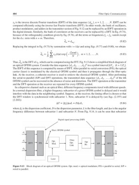
Thus, d is the DFT of s , which can be computed using the FFT. Fig. 9.13 shows a simplified block diagram of
k
m
k
an optical OFDM system. Consider the data sequence {d , d , … , d } in a symbol interval [kT , (k + 1)T ].
s
s
1
N
2
The IDFT of this sequence is computed by means of IFFT. After parallel-to-serial conversion (P/S), the optical
carrier (laser) is modulated by the electrical OFDM symbol and then it propagates through the fiber-optic
link. At the receiver, a coherent receiver is used to retrieve the electrical OFDM symbol. After performing
k
the serial-to-parallel (S/P) and DFT operations, the transmitted data sequence {d , d , … , d } of the kth
1 2 N
OFDM symbol can be recovered in the absence of noise and distortion. The IDFT operation at the transmitter
and the DFT operation at the receiver are repeated for every OFDM symbol.
In a dispersive channel such as an optical fiber, different frequency components travel with different speeds.
In a normal dispersion fiber, a higher-frequency subcarrier of a given OFDM symbol is delayed and it would
interfere with the data in the neighboring symbol. Suppose, at the receiver, the timing offset is chosen so that
the DFT window is synchronized with subcarrier 1. Now, subcarrier N is delayed by (see Eqs. (2.197) and
(2.203))
ΔT = | |ΔL = DΔL, (9.84)
2
where is the dispersion coefficient, D is the dispersion parameter, L is the fiber length, and Δ is the angular
2
frequency difference between subcarrier 1 and subcarrier N. From Fig. 9.14, it can be seen that subcarrier
Digital signal processing (DSP)
Elect. OFDM symbol
d 1
d 1
Fiber
d 2 Opt. Opt
IFFT P/S Mod. Opt. S/P FFT d 2
Link Rx
d N
d N
Laser
Figure 9.13 Block diagram of an optical OFDM system. Opt. mod. = optical modulator, P/S = parallel to serial, S/P =
serial to parallel.