
Page 425 - Fiber Optic Communications Fund
P. 425
406 Fiber Optic Communications
Although subcarrier N moves out of the DFT due to fiber dispersion, because of its identical copy in the
guard interval, the signal corresponding to subcarrier N at the receiver is the same as that at the transmitter
except for a phase jump, as shown in Fig. 9.15. The phase jump can be removed after channel estimation at
the receiver. As long as the maximum delay ΔT introduced by the dispersive channel is less than the guard
interval T , the subcarriers are orthogonal at the receiver. The maximum delay ΔT is
g
ΔT = | |(2NΔf)L, (9.85)
2
where Δf = 1∕T is the frequency spacing between subcarriers. Therefore, the guard interval should be chosen
s
so that
| |(2NΔfL) < T . (9.86)
2 g
To preserve the orthogonality of all the subcarriers, the last few cycles of each subcarrier should be copied
to the guard interval. Although the guard interval increases the tolerance against delay due to dispersion, it
reduces the efficiency since the guard interval is discarded by the receiver.
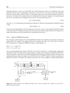
9.4.2 Optical OFDM Transmitter
Fig. 9.16 shows a block diagram of an optical OFDM transmitter. First, the binary serial input is converted to
parallel (S/P). For example, a bit sequence {00110111} is broken into {00}, {11}, {01}, and {11}. Each of
these subsequences is mapped into QPSK data using a symbol mapper, i.e.,
√
{00} → (−1 − i)∕ 2 = d 1
√
{11} → (1 + i)∕ 2 = d 2
and so on. By breaking the bit sequence {00110111} into {0011} and {0111}, a symbol mapper could map it
onto QAM-16 data. The output of the symbol mapper is complex data which passes through the IFFT block.
After the parallel-to-serial conversion (P/S) and guard interval insertion, the digital signal is converted to an
analog signal using a digital-to-analog converter (DAC). In fact, the IFFT output is complex in general and,
therefore, two DACs are needed. The outputs of the DACs are used to modulate an optical IQ modulator.
Binary
00
input
S/P Symbol IFFT P/S
0011...1 mapper
11
Guard OFDM Optical IQ To fiber channel
interval DAC modulator
Laser
DSP
Figure 9.16 Block diagram of the OFDM transmitter. S/P = serial to parallel, P/S = parallel to serial, DAC =
digital-to-analog converters.