
Page 428 - Fiber Optic Communications Fund
P. 428
Channel Multiplexing Techniques 409
The maximum reach is given by
T g 1.28 × 10 −9
L max = =
| |(2NΔf) 22 × 10 −27 × 2 × 128 × 78.125 × 10 6
2
= 925 km. (9.91)
9.5 Time-Division Multiplexing
In the case of frequency-division multiplexing, parallel streams of data are modulated by carriers with differ-
ent frequencies so that the data spectra do not overlap (see Fig. 9.4). Instead, the parallel streams of data can be
converted to serial data in such a way that the individual streams do not overlap in time. This type of multiplex-
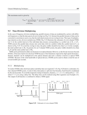
ing is known as time-division multiplexing (TDM). Fig. 9.19 illustrates the schematic of a two-channel TDM.
Let T be the symbol interval of the individual data streams corresponding to a symbol rate of B = 1∕T .
s s s
TDM converts the parallel data streams into serial data with two symbols within the symbol interval T ,as
s
shown in Fig. 9.19. To avoid the overlap in time, the pulse widths should be less than T ∕2. In this example,
s
the total symbol rate is 2B . In general, for an N-channel TDM system, the pulse widths should be less than
s
T ∕N and the total symbol rate is NB .
s
s
TDM can be performed in either an electrical or an optical domain. However, as the bit rate increases beyond
40 Gb/s, if becomes hard to do electrical TDM because of the limitations imposed by high-speed electronics.
Instead, channels can be multiplexed in the optical domain and such a scheme is known as optical TDM
(OTDM). Because of the wide bandwidth of optical devices, OTDM can be used to obtain a total bit rate of
several terabits per seconds.
9.5.1 Multiplexing
To realize OTDM, ultra-short laser pulses and delay lines are required [7, 43]. Fig. 9.20 shows a schematic of a
four-channel OTDM system. A train of ultra-short pulses is split into four branches. Each branch is modulated
by the electrical data. To avoid the temporal overlap of channels, channel j, j = 1, 2, 3, 4, is delayed by (j − 1)T,
where T = T ∕4, using a delay line. The delay lines can be realized using fiber segments (see Example 2.5).
s
The output of all branches is combined to obtain a TDM signal.
Ch. 2 Ch. 2 Ch. 2 Ch. 2
Ch. 1 Ch. 1 Ch. 1 Ch. 1 Ch. 1
T s
T s
TDM
Ch. 2 TDM signal
T s
Figure 9.19 Schematic of a two-channel TDM.