
Page 431 - Fiber Optic Communications Fund
P. 431
412 Fiber Optic Communications
Solution:
The bit interval for a 10-Gb/s signal is equal to
1
ps = 100 ps. (9.93)
10 × 10 9
The bit interval for a 40-Gb/s signal is equal to
1
ps = 25 ps. (9.94)
40 × 10 9
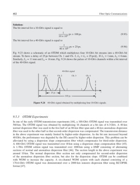
Fig. 9.23 shows a schematic of an OTDM which multiplexes four 10-Gb/s bit streams into a 40-Gb/s bit
stream. To have a delay of 25 ps between Ch. 1 and Ch. 2, L = L + 25 ps/ .If L = 1 mm, L = 6 mm.
2
2
1
1
1
Similarly, L = 11 mm and L = 16 mm. Fig. 9.24 shows the pulses of 10-Gb/s channels within a bit interval
4
3
of the 40-Gb/s signal.
40-Gb/s signal
Ch. 1 Ch. 2 Ch. 3 Ch. 4
25 ps t
100 ps
Figure 9.24 40-Gb/s signal obtained by multiplexing four 10-Gb/s signals.
9.5.3 OTDM Experiments
In one of the early OTDM transmission experiments [44], a 100-Gb/s OTDM signal was transmitted over
560 km. The OTDM signal was obtained by multiplexing 16 channels at a bit rate of 6.3 Gb/s. A 40-km
normal dispersion fiber was used in the first half of an 80-km fiber span and a 40-km anomalous dispersion
fiber was used in the other half so that second-order dispersion was compensated. The transmission distance
in the above experiment was mainly limited by higher-order dispersion. As the bit rate increased beyond
40 Gb/s, the performance was degraded by the ISI caused by higher-order dispersion. This problem can be
alleviated by using a dispersion slope compensation fiber which compensates for third-order dispersion.
A 400-Gb/s OTDM signal was transmitted over 40 km using a dispersion slope compensation fiber [45].
A 1-Tb/s OTDM soliton signal was transmitted over 1000 km using a DMF consisting of alternating
sections of normal and anomalous dispersion fiber [46]. The section length in the above experiment was
around 10 km. The normal dispersion fiber section not only compensated for second-order dispersion
of the anomalous dispersion fiber section, but also for the dispersion slope. OTDM can be combined
with WDM to increase the capacity. A six-channel WDM system with each channel consisting of a
170.6-Gb/s OTDM signal was demonstrated over a 2000-km nonzero dispersion fiber using RZ-DPSK
format [47].