
Page 429 - Fiber Optic Communications Fund
P. 429
410 Fiber Optic Communications
Electrical data
Mod
Ch. 1
Ch. 1 23 4 1 2 3 4 1 2 3 4
Mod T
T Ch. 2
s
T s
Laser
TDM signal
Mod 2T
Ch. 3
Mod 3T
Ch. 4
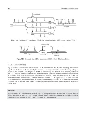
Figure 9.20 Schematic of a four-channel OTDM. Mod = optical modulator and T refers to a delay of T ∕4.
s
Electrical clock
Ch. 1 2 1 2 1 2 signal Ch. 1 1 1
MZM
OTDM signal Demultiplexed
channel 1
Figure 9.21 Schematic of an OTDM demultiplexer. MZM = Mach–Zehnder modulator.
9.5.2 Demultiplexing
Fig. 9.21 shows a schematic of a two-channel OTDM demultiplexer. The MZM is driven by the electrical
signal at a clock rate of B . To demultiplex channel 1, the amplitude of the electrical driving voltage is
s
chosen so that channel 1 is at the peak of the MZM transmittivity and channel 2 is at the null (see Section
4.6.2.2). Therefore, the modulator transmits channel 1 without significant attenuation while it rejects channel
2. A similar MZM with the appropriate delay transmits channel 2 while rejecting channel 1. MZMs can
easily be cascaded to demultiplex a channel from an N-channel OTDM signal [7, 43]. To avoid cross-talk
from other channels, the extinction ratio of the modulator should be high [43]. A moderate extinction ratio
(∼ 15 dB) can be realized with MZMs. To enhance the extinction further, electroabsorption modulators
can be used.
Example 9.5
A pulse incident on a 3-dB splitter as shown in Fig. 9.22 has a pulse width (FWHM) = 5 ps and a peak power =
5 mW. The length of fiber 1 is 1 mm. Find the length of fiber 2 so that the separation between pulses after the
combiner is 25 ps. Assume = 0.5 × 10 −8 s/m and = 0 for both fibers.
1
2