
Page 426 - Fiber Optic Communications Fund
P. 426
Channel Multiplexing Techniques 407
Real part of OFDM data
DAC
MZM-I
Laser
MZM-Q π/2
DAC
Imaginary part of OFDM data
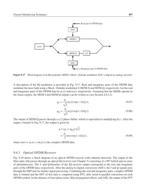
Figure 9.17 Block diagram of an IQ modulator. MZM = Mach–Zehnder modulator, DAC = digital-to-analog converter.
A description of the IQ modulator is provided in Fig. 9.17. Real and imaginary parts of the OFDM data
modulate the laser light using a Mach–Zehnder modulator-I (MZM-I) and MZM-Q, respectively. Let the real
and imaginary parts of the OFDM data be m (t) and m (t), respectively. Assuming that the MZMs operate in
r i
the linear regime, the MZM-I and MZM-Q outputs can be written as (see Section 4.6.2.2)
A c
q = √ m (t) exp (−i2f t), (9.87)
I r c
2
A c
q = √ m (t) exp (−i2f t). (9.88)
i
Q
c
2
The output of MZM-Q passes through a ∕2 phase shifter, which is equivalent to multiplying by i.After the
output y-branch in Fig. 9.17, the output is given by
√
q =(q + iq )∕ 2
I
Q
A c
= m(t) exp (−i2f t), (9.89)
c
2
where m(t)= m (t)+ im (t) is the complex OFDM data.
r i
9.4.3 Optical OFDM Receiver
Fig. 9.18 shows a block diagram of an optical OFDM receiver with coherent detection. The output of the
∘
fiber-optic link passes through an optical IQ receiver (see Chapter 5) consisting of a 90 hybrid and an array
of photodetectors. The I- and Q-branches of the IQ receiver output correspond to the real and imaginary
parts of the OFDM data, respectively. After the analog-to-digital conversion (ADC), the I and Q signals pass
through the DSP unit for further signal processing. Combining the real and imaginary parts, complex OFDM
data is formed and the DFT of this data is computed using FFT, after serial-to-parallel conversion on each
OFDM symbol. In the absence of laser phase noise, fiber propagation effects, and ASE, the output of the FFT