
Page 419 - Fiber Optic Communications Fund
P. 419
400 Fiber Optic Communications
Wavefront at 1
Δx
j
a
Wavefront at 2
j * 1
Δ
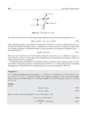
Figure 9.11 Wavefronts at and .
1 2
From Eqs. (9.50) and (9.54), it follows that the phase difference between adjacent waveguides at is
2
( )= ( )− j−1 ( )= kΔΔl. (9.56)
j
2
2
2
Thus, although the phases of the adjacent waveguides are identical at , they are shifted by kΔΔl at .
2
1
Consider two adjacent waveguides j and j − 1 separated by a, as shown in Fig. 9.11. Suppose the optical field
in waveguide j propagates an additional distance Δx, then the phases of the output of waveguides j and j − 1
become identical, i.e.,
kΔΔl = ( )Δx. (9.57)
2
Thus, the wave front (the locus of all the points having the same phase) at is tilted by an angle Δ=
2
Δx∕a. Therefore, in Fig. 9.10, the output of the waveguide array corresponding to wavelength focuses on
2
a different port than the wavelength .
1
A waveguide grating demultiplexer on InP which resolves 16 channels with a channel spacing of 1.8 nm
and with low polarization sensitivity was demonstrated in 1994 [11]. A 4-channel phased-array wavelength
demultiplexer on InGaAsP/InP with a channel spacing of 1 nm was demonstrated in 1996 [12].
Example 9.3
6
A1 × 2 AWG demultiplexer has to be designed. = 1550 nm, = 1550.8nm, = 5.87 × 10 m −1 at ,
2
0
1
1
= 4.86 × 10 −9 s/m at . (a) Find the lengths of the adjacent waveguides l and l such that the phase
1
1
1
2
shifts and at the fiber outputs at are integral multiples of 2. (b) Calculate and at . Assume
2
2
1
1
1
2
= = 0.
1
2
Solution:
(a) Let
( )l = 2m , (9.58)
1 1
1
( )l = 2m . (9.59)
2
1 2
Here, m and m could be any integers. Let m = 100 and m = 110:
2
1
1
2
6
−1
( )= = 5.87 × 10 m , (9.60)
1
0
2 × 100
l = = 107.04 μm, (9.61)
1
0