Page 416 - Fiber Optic Communications Fund
P. 416

Channel Multiplexing Techniques                                                    397


            Consider an optical wave with propagation constant k = 2n∕ , where n is the refractive index of the MZ
                                                      1
                                                               1
           interferometer. If
                                        k ΔL =(2m + 1), m = 0, ±1, ±2,                    (9.41)
                                        1
           we have
                                                         2
                                                 P out,1  = A ,
                                                         0
                                                 P    = 0.                                  (9.42)
                                                  out,2
           So, all the input power appears in port 1. Given another optical wave with k = 2n∕ and if
                                                                               2
                                                                       2
                                           k ΔL = 2l, l = 0, ±1, ±2,                      (9.43)
                                            2
           we find that all the input power appears in port 2. Therefore, if we choose the wavelengths  and  such
                                                                                      1
                                                                                            2
           that
                                               nΔL   (2m + 1)
                                                   =        ,                               (9.44)
                                                      2
                                                 1
                                               nΔL
                                                   = l,                                     (9.45)
                                               
                                                 2
           the optical fields with wavelengths  and  appear in ports 1 and 2, respectively. From Eqs. (9.44) and
                                         1     2
           (9.45), we obtain
                                                 ′
                                            (2m + 1)
                                           1 2
                                                         ′
                                  −  =            , m = m − l = 0, ±1, ±2.              (9.46)
                                  2
                                      1
                                             2nΔL
           Since f = c∕ , j = 1, 2, from Eqs. (9.41) and (9.43), we obtain
                j
                      j
                                                       ′
                                                    (2m + 1)c
                                               Δf =         ,                               (9.47)
                                                      2nΔL
           where Δf = f − f is the channel spacing. For example, wavelengths  = 1540 nm and  = 1540.4nm are
                                                                                  2
                         2
                                                                   1
                     1
           multiplexed in a WDM system. At the receiver, these wavelengths can be separated if
                                            (2m + 1)
                                           1 2
                                     ΔL =            , m = 0, ±1, ±2, … .                   (9.48)
                                           ( −  )2n
                                             2   1
           If we choose m = 0, we find ΔL = 2 mm.
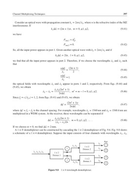
            A1 × N demultiplexer can be constructed by cascading the 1 × 2 demultiplexer of Fig. 9.6. Fig. 9.8 shows
           a schematic of a 1 × 4 demultiplexer. Suppose the input consists of four channels with wavelengths  ,  ,
                                                                                            1
                                                                                               2
                                                                               Port

                                                               1  2      1   1
                                                        1,  3
                                                   1           Demux 2      2
                                      1  2                                 2
                           1,  2,  3,  4
                                         Demux 1                            3  3
                                                   2             1  2
                                                              Demux 3     4   4
                                                         2,  4
                                     Figure 9.8  1 × 4 wavelength demultiplexer.
   411   412   413   414   415   416   417   418   419   420   421