Page 415 - Fiber Optic Communications Fund
P. 415

396                                                               Fiber Optic Communications


                                                       [  co1  ]
                                                        A out,1
                                                 A co1  =     .                               (9.33)
                                                  out
                                                        A co1
                                                         out,2
            Optical fields in the upper and lower arms of the interferometer undergo phase shifts k(L +ΔL∕2) and k(L −
            ΔL∕2), respectively, where k is the propagation constant and ΔL is the path-length difference between two
            arms. Therefore, the inputs of the 3-dB coupler 2 can be written as

                                                 A 0
                                           A co2  = √ exp [ik(L +ΔL∕2)],                      (9.34)
                                            in,1
                                                   2
                                                 iA 0
                                            co2
                                           A   = √ exp [ik(L −ΔL∕2)].                         (9.35)
                                            in,2
                                                   2
            The outputs of the 3-dB coupler are
                                                 co2         co2
                                               A   = M      A  ,                              (9.36)
                                                 out   coupler  in
                                          A co2  = A exp (ikL)i sin (kΔL∕2),                  (9.37)
                                           out,1  0
                                          A co2  = A exp (ikL)i cos (kΔL∕2).                  (9.38)
                                           out,2  0
            The corresponding output powers are
                                                          2
                                                     2
                                                             2
                                         P    = |A co2  | = A sin (kΔL∕2),                    (9.39)
                                          out,1   out,1   0
                                                     2
                                                          2
                                                             2
                                         P out,2  = |A co2  | = A cos (kΔL∕2).                (9.40)
                                                          0
                                                  out,2
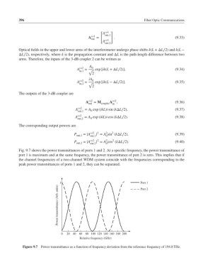
            Fig. 9.7 shows the power transmittances of ports 1 and 2. At a specific frequency, the power transmittance of
            port 1 is maximum and at the same frequency, the power transmittance of port 2 is zero. This implies that if
            the channel frequencies of a two-channel WDM system coincide with the frequencies corresponding to the
            peak power transmittances of ports 1 and 2, they can be separated.

                                  1                                         Port 1
                                 Power transmittance (Arb. units)
                                                                            Port 2


                                  0  20  40  60  80 100 120 140 160 180 200
                                            Relative frequency (GHz)

              Figure 9.7 Power transmittance as a function of frequency deviation from the reference frequency of 194.8 THz.
   410   411   412   413   414   415   416   417   418   419   420