Page 458 - Fiber Optic Communications Fund
P. 458
Nonlinear Effects in Fibers                                                        439


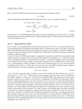
           Here, d denotes the difference between the inverse group speed of channel n and  ,
                                                                             1
                 n
                                                 d =  Ω .                               (10.142)
                                                         n
                                                  n
                                                       2
           When the bandwidth of the WDM and/or the dispersion slope is large, d should be modified as
                                                                    n
                                d =  ( +Ω )−  ( )
                                 n   1  0   n    1  0
                                                          2
                                            d |       1 d  |   2
                                              1
                                                            1
                                  =  ( )+  |   Ω +       |    Ω −  ( )
                                     1  0      |     n      2 |    n   1  0
                                            d |= 0  2 d |= 0
                                           3  2
                                  =  Ω +  Ω .                                           (10.143)
                                       n
                                     2
                                              n
                                           2
           In Section 10.7.1.1, the XPM-induced timing shift is discussed qualitatively. In Section 10.7.1.2, a simple
           analytical expression for the XPM efficiency is obtained and the impact of XPM on transmission performance
           is covered in Section 10.7.1.3.
           10.7.1.1  Timing Shift Due to XPM
           Let us consider a two-channel WDM system described by Eq. (10.141) with N = 2. Owing to the Kerr effect,
           two propagating pulses with different wavelengths induce a nonlinear phase shift on each other. This phase
           shift is time-dependent and, therefore, the instantaneous frequency across a pulse in a channel is modified. In
           a dispersive fiber, this frequency shift is translated into a timing shift since different frequency components
           propagate at different speeds.
            Fig. 10.10 shows two WDM channel inputs. A single pulse is launched at symbol slot 0 in each channel, and
                                                                                      2
           initially the pulses are aligned. We assume that the fiber dispersion is anomalous ( =−10 ps /km) and the
                                                                             2
           center wavelength of channel 2 is longer than that of channel 1, so channel 2 propagates slower than channel
           1. Our reference frame is fixed to channel 1 and the pulse in channel 2 moves with the inverse walk-off speed
           of d =  Ω (ignoring  ) relative to channel 1, where Ω is the channel spacing. Fig. 10.11 shows the pulses
                  2
              2
                              3
           of channels at the end of a L = 80 km span. As can be seen, due to the different channel speeds, channel 1
           walked off channel 2. The pulse separation at the end of the span is given by
                                              ΔT = d L ≅ 250 ps.                          (10.144)
                                                    2
            Fig. 10.12 shows the pulse shape of channel 1 at the end of the fiber for three different cases. (1) Lin-
                                  −1
           ear case (Lin):  = 0W −1  km , which shows the linear response of the fiber-optics system. (2) SPM case
           (Lin+SPM): channel 2 is turned off. (3) XPM case (Lin+SPM+XPM): both channels are present. Since
           anomalous dispersion was assumed, in the presence of nonlinearity (Lin+SPM), the output pulse width is
           narrower compared with the linear case (Lin). From Fig. 10.12, it can also be seen that when both channels
           are present (Lin+SPM+XPM), the center of the pulse has moved to the right. As the fast channel (channel 1)
           walks off, it induces the phase modulation on the slower channel (channel 2), and vice versa. In Fig. 10.10,
           the pulses are initially aligned and during the propagation, the leading edge of the slow channel overlaps
           with the trailing edge of the fast channel. The slope is positive at the leading edge of the pulse in channel
           2. This leads to a negative instantaneous frequency shift of the pulse in channel 1 (see Eq. (10.167)) or, in
           other words, channel 1 is red-shifted. Since red-shifted components travel slowly in an anomalous dispersion
           fiber, the pulse of channel 1 arrives late or, in other words, there is a timing shift due to XPM (Fig. 10.12).
           Since this timing shift is bit-pattern dependent, it leads to timing jitter in soliton systems [12, 13]. The timing
           fluctuations leads to amplitude fluctuations of the signal samples used for decision and, hence, performance
           degradations (see Section 10.7.1.3).

