
Page 55 - Fiber Optic Communications Fund
P. 55
36 Fiber Optic Communications
Cladding
Core
Polymer jacket
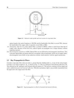
n 1
Index n 2
n 0
Radial distance
Figure 2.1 Refractive index profile and cross-section of a step-index fiber.
optical signals, the carrier frequency is 200 THz and the bandwidth of the fiber is several THz, whereas
the bandwidth of the copper cable is typically several GHz or MHz.
(ii) Attenuation: The loss of a silica optical fiber is around 0.2 dB/km, which is much lower than that of
copper cable. Because of the lower loss, optical signals can propagate over a longer distance without
requiring repeaters.
(iii) Electromagnetic interference (EMI): Optical fibers are not affected by electromagnetic interference. This
is because optical fibers are purely dielectric waveguides with no metal parts. In the case of copper cables,
electromagnetic noise fields set up conduction currents which interfere with the signal transmission.
2.3 Ray Propagation in Fibers
Consider a step-index fiber with core index n greater than the cladding index n .Let be the critical angle.
1 2 c
Consider a ray with an angle > , as shown in Fig. 2.2. This ray undergoes total internal reflection at B.
c
The reflected ray BC undergoes total internal reflection again at C. This process continues till the output end
and is called frustrated total internal reflection. With this mechanism, light is successfully transmitted from
the input end to the output end of the fiber.
n 2 B D
øø
Core
n 1
øø
A C E
Figure 2.2 Signal propagation in a fiber by frustrated total internal reflection.