Page 57 - Fiber Optic Communications Fund
P. 57

38                                                                Fiber Optic Communications


                                            Jacket                     Jacket
                                       Cladding                           Cladding
                                 i max
                                  i      Core                              Core
                                                             i
                                            Jacket                     Jacket
                                             (a)                        (b)

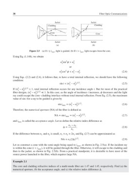
                         Figure 2.5 (a) If i ≤ i max , light is guided. (b) If i > i max , light escapes from the core.
            Using Eq. (1.148), we obtain
                                                 2
                                                    2
                                                n sin > n 2
                                                 1        2
                                                       or
                                                 2
                                                    2
                                                          2
                                                              2
                                                n cos < n − n .                              (2.4)
                                                 1        1   2
            Using Eqs. (2.2) and (2.4), it follows that, to have a total internal reflection, we should have the following
            condition:
                                                       2
                                                           2 1∕2
                                                sin i < (n − n )  .                            (2.5)
                                                       1   2
                    2 1∕2
                2
            If (n − n )  > 1, total internal reflection occurs for any incidence angle i. But for most of the practical
                1   2
                         2
                             2 1∕2
            fiber designs, (n − n )  ≪ 1. In this case, as the angle of incidence i increases,  decreases and the light
                         1   2
            ray could escape the core–cladding interface without total internal reflection. From Eq. (2.5), the maximum
            value of sin i for a ray to be guided is given by
                                                        2
                                                            2 1∕2
                                              sin i max  =(n − n )  .                          (2.6)
                                                            2
                                                        1
            Therefore, the numerical aperture (NA) of the fiber is defined as
                                                               2 1∕2
                                                           2
                                            NA = sin i max  =(n − n )  ,                       (2.7)
                                                           1
                                                               2
            and i max  is called the acceptance angle. Let us define the relative index difference as
                                                      n − n 2
                                                       1
                                                  Δ=        .                                  (2.8)
                                                        n 1
            If the difference between n and n is small, n + n ≈ 2n and Eq. (2.7) can be approximated as
                                                          1
                                        2
                                                     2
                                  1
                                                 1
                                                 NA ≈ n (2Δ) 1∕2 .                             (2.9)
                                                       1
            Let us construct a cone with the semi-angle being equal to i max , as shown in Fig. 2.5(a). If the incident ray
            is within the cone (i < i max ), it will be guided through the fiber. Otherwise, it will escape to the cladding and
            then to the jacket, as shown in Fig. 2.5(b). From a practical standpoint, it is desirable to have most of the
            source power launched to the fiber, which requires large NA.
            Example 2.1
            The core and cladding refractive indices of a multi-mode fiber are 1.47 and 1.45, respectively. Find (a) the
            numerical aperture, (b) the acceptance angle, and (c) the relative index difference Δ.
   52   53   54   55   56   57   58   59   60   61   62