Page 61 - Fiber Optic Communications Fund
P. 61

42                                                                Fiber Optic Communications


                                   Power (arb. units)


                                                                          Time
                                            50 ns
                                            500 ns    500 ns
                                                        (a)

                                   Power (arb. units)


                                                 10 ns                    Time
                                                 50 ns
                                                        (b)

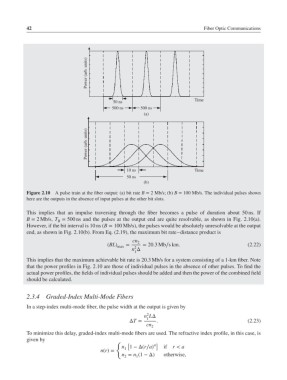
            Figure 2.10 A pulse train at the fiber output: (a) bit rate B = 2Mb/s; (b) B = 100 Mb/s. The individual pulses shown
            here are the outputs in the absence of input pulses at the other bit slots.

            This implies that an impulse traversing through the fiber becomes a pulse of duration about 50 ns. If
            B = 2Mb/s, T = 500 ns and the pulses at the output end are quite resolvable, as shown in Fig. 2.10(a).
                        B
            However, if the bit interval is 10 ns (B = 100 Mb/s), the pulses would be absolutely unresolvable at the output
            end, as shown in Fig. 2.10(b). From Eq. (2.19), the maximum bit rate–distance product is
                                                   cn 2
                                          (BL) max  =  = 20.3Mb∕skm.                          (2.22)
                                                    2
                                                   n Δ
                                                    1
            This implies that the maximum achievable bit rate is 20.3 Mb/s for a system consisting of a 1-km fiber. Note
            that the power profiles in Fig. 2.10 are those of individual pulses in the absence of other pulses. To find the
            actual power profiles, the fields of individual pulses should be added and then the power of the combined field
            should be calculated.


            2.3.4   Graded-Index Multi-Mode Fibers
            In a step-index multi-mode fiber, the pulse width at the output is given by
                                                         2
                                                        n LΔ
                                                         1
                                                  ΔT =      .                                 (2.23)
                                                        cn 2
            To minimize this delay, graded-index multi-mode fibers are used. The refractive index profile, in this case, is
            given by
                                             {
                                                  [         ]
                                               n 1 −Δ(r∕a)     if  r < a
                                                1
                                        n(r)=
                                               n = n (1 −Δ)    otherwise,
                                                2
                                                     1
   56   57   58   59   60   61   62   63   64   65   66