Page 59 - Fiber Optic Communications Fund
P. 59

40                                                                Fiber Optic Communications


                                                                               Input pulse
                   Input pulse                      1      2     3


                                                                                     Output pulse
                             12 3

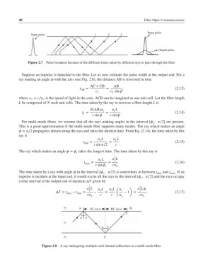
                 Figure 2.7  Pulse broadens because of the different times taken by different rays to pass through the fiber.


              Suppose an impulse is launched to the fiber. Let us now estimate the pulse width at the output end. For a
            ray making an angle  with the axis (see Fig. 2.8), the distance AB is traversed in time
                                                 AC + CB      AB
                                            t AB  =       =       ,                           (2.13)
                                                     1     sin 
                                                             1
            where  = c∕n is the speed of light in the core. ACB can be imagined as one unit cell. Let the fiber length
                         1
                   1
            L be composed of N such unit cells. The time taken by the ray to traverse a fiber length L is
                                                 N(AB)n 1    n L
                                                              1
                                             t =          =      .                            (2.14)
                                              L
                                                   c sin   c sin 
              For multi-mode fibers, we assume that all the rays making angles in the interval [ ,∕2] are present.
                                                                                  c
            This is a good approximation if the multi-mode fiber supports many modes. The ray which makes an angle
             = ∕2 propagates almost along the axis and takes the shortest time. From Eq. (2.14), the time taken by this
            ray is
                                                      n L    n L
                                                              1
                                                       1
                                              t  =         =     .                            (2.15)
                                              min
                                                   c sin ∕2  c
            The ray which makes an angle  =  takes the longest time. The time taken by this ray is
                                          c
                                                              2
                                                      n L    n L
                                                       1
                                                              1
                                              t   =        =    .                             (2.16)
                                               max
                                                    c sin   cn
                                                         c     2
            The time taken by a ray with angle  in the interval [ ,∕2] is somewhere in between t  and t  .Ifan
                                                        c                           min    max
            impulse is incident at the input end, it would excite all the rays in the interval [ ,∕2] and the rays occupy
                                                                            c
            a time interval at the output end of duration ΔT given by
                                                                           2
                                                 2
                                                n L   n L  n L  ( n   )   n LΔ
                                ΔT = t  − t   =  1  −  1  =  1    1  − 1  =  1  ,             (2.17)
                                     max   min
                                                cn     c    c    n         cn
                                                  2               2          2
                                    n 2     A    AC sin ø   BC sin ø  B
                                            ø  ø
                                    n 1
                                                        ø  ø
                                    n 2                  C
                        Figure 2.8 A ray undergoing multiple total internal reflections in a multi-mode fiber.
   54   55   56   57   58   59   60   61   62   63   64