
Page 56 - Fiber Optic Communications Fund
P. 56
Optical Fiber Transmission 37
Reflective coating
Silica core
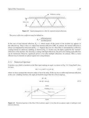
Figure 2.3 Signal propagation in a fiber by repeated normal reflections.
The power reflection coefficient may be defined as
reflected power
R = . (2.1)
p
incident power
In the case of total internal reflection, R = 1, which means all the power of the incident ray appears in
p
the reflected ray. That is why it is called total internal reflection (TIR). In contrast, the normal reflection is
always accompanied by refraction and R < 1. Suppose the core of a silica fiber is surrounded by a reflective
p
coating instead of a dielectric cladding, as shown in Fig. 2.3. In this case, the light is guided by the “normal”
reflections at the interface. By choosing a coating with high reflectivity, the power loss during each reflection
can be minimized. However, significant power is lost after multiple reflections. In contrast, TIR is a more
efficient way to transmit an optical signal over a long distance.
2.3.1 Numerical Aperture
Consider a ray which is incident on the fiber input making an angle i as shown in Fig. 2.4. Using Snell’s law,
we have
sin i = n sin = n cos , (2.2)
1
1
where we have assumed the refractive index of air to be unity. If this ray has to suffer total internal reflection
at the core–cladding interface, the angle should be larger than the critical angle ,
c
> ,
c
sin > sin . (2.3)
c
Jacket
A Cladding, n= n 2 B
ø
Air, n= 1 θ Core, n =n 1
i
C
Jacket
Figure 2.4 Numerical aperture of the fiber. If the incidence angle i is less than the acceptance angle, it undergoes total
internal reflection.