
Page 74 - Fiber Optic Communications Fund
P. 74
Optical Fiber Transmission 55
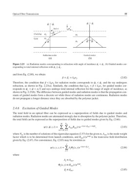
Figure 2.23 (a) Radiation modes corresponding to refraction with angle of incidence < . (b) Guided modes cor-
i c
responding to total internal reflection with ≥ .
i c
and from Eq. (2.80), we obtain
= = k n . (2.82)
c 0 2
Therefore, the condition that < k n for radiation modes corresponds to < and the ray undergoes
0 2 i c
refraction, as shown in Fig. 2.23(a). Similarly, the condition that k n < < k n for guided modes cor-
0 2
0 1
responds to <<∕2 and rays undergo total internal reflection for this range of angle of incidence, as
c
shown in Fig. 2.23(b). The difference between guided modes and radiation modes is that the propagation con-
stants of guided modes form a discrete set while those of radiation modes are continuous. Radiation modes
do not propagate a longer distance since they are absorbed by the polymer jacket.
2.4.6 Excitation of Guided Modes
The total field in an optical fiber can be expressed as a superposition of fields due to guided modes and
radiation modes. Radiation modes are attenuated strongly due to absorption by the polymer jacket. Therefore,
the total field can be expressed as the superposition of fields due to guided modes given by Eq. (2.66):
M N m
∑ ∑ −i(t− mn z−im)
(r,, z, t)= A R (r)e , (2.83)
mn mn
m=−M n=1
where N is the number of solutions of the eigenvalue equation (2.57) for the given m, A is the mode weight
m mn
factor which is to be determined from launch conditions, and R (r)e im is the transverse field distribution
mn
given by Eq. (2.67). For convenience, Eq. (2.83) may be rewritten as
J
∑ −i(t− j z)
(x, y, z, t)= A Φ (x, y)e , (2.84)
j
j
j=1
where
A ≡ A ,
j mn
Φ (x, y) ≡ R (r)e im ,
j mn
≡ , (2.85)
mn
j