
Page 127 - Computer Graphics Handout
P. 127
individual rotations. Our strategy is to carry out two rotations to align the axis of rotation, v,
with the z-axis. Then we can rotate by θ about the z-axis, after which we can undo the two
rotations that did the aligning. Our final rotation matrix will be of the form
R = Rx(−θx)Ry(−θy)Rz(θ)Ry(θy)Rx(θx).
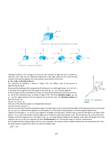
This sequence of rotations is shown in Figure 3.54. The difficult part of the process is
determining θx and θy.
2
2
2
We proceed by looking at the components of v. Because v is a unit-length vector, α x+ α y+ α z=
1. We draw a line segment from the origin to the point (αx , αy , αz). This line segment
has unit length and the orientation of v. Next, we draw the perpendiculars from the point (αx ,
αy , αz) to the coordinate axes, as shown in Figure 3.55. The three direction angles—φx, φy,
φz—are the angles between the line segment (or v) and the axes. The direction cosines are
given by cos φx = αx ,
cos φy = αy ,cos φz = αz .
Only two of the direction angles are independent, because
cos2 φx+ cos2 φy+ cos2 φz= 1.
We can now compute θx and θy using these angles. Consider Figure 3.56. It shows that the effect of the desired rotation on the point
(αx , αy , αz) is to rotate the line segment into the plane y = 0. If we look at the projection of the line segment (before the
rotation) on the plane x = 0, we see a line segment of length d on this plane. Another way to envision this figure is to think of the
plane x = 0 as a wall and consider a distant light source located far down the positive x-axis. The line that we see on the wall is the
shadow of the line segment from the origin to (αx , αy , αz). Note that the length of the shadow is less than the length of the line
segment. We can say the line segment has been foreshortened to d = The desired angle of rotation is determined
by the angle that this shadow makes with the z-axis. However, the rotation matrix is determined by the sine and cosine of θx. Thus,
we never need to compute θx; rather, we need to compute only
127