
Page 129 - Computer Graphics Handout
P. 129
22
dependent on what the application programmer decides to do . In a modern implementation of OpenGL, the application
programmer not only can choose which frames to use but also where to carry out the transformations between frames. Some will
best be carried out in the application, others in a shader.
As we develop a method for specifying and carrying out transformations, we should emphasize the importance of state. Although
very few state variables are predefined in OpenGL, once we specify various attributes and matrices, they effectively define the state
of the system. Thus, when a vertex is processed, how it is processed is determined by the values of these state variables.
The two transformations we will use most often are the model-view transformation and the projection transformation. The model-
view transformation brings representations of geometric objects from application or model frame to the camera frame. The
projection matrix will both carry out the desired projection and also change the representation to clip coordinates.We will use only
the model-view matrix in this chapter. The model-view matrix normally is an affine-transformation matrix and has only 12 degrees
of freedom, as discussed in Section 3.7. The projection matrix, as we will see in Chapter 4, is also a 4 × 4 matrix, but it is not affine.
3.11.1 Current Transformation Matrices
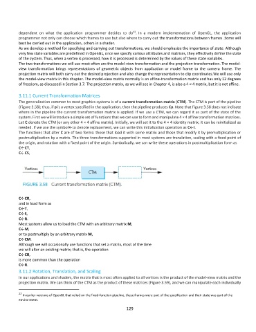
The generalization common to most graphics systems is of a current transformation matrix (CTM). The CTM is part of the pipeline
(Figure 3.58); thus, if p is a vertex specified in the application, then the pipeline produces Cp. Note that Figure 3.58 does not indicate
where in the pipeline the current transformation matrix is applied. If we use a CTM, we can regard it as part of the state of the
system. First we will introduce a simple set of functions that we can use to form and manipulate 4 × 4 affine transformation matrices.
Let C denote the CTM (or any other 4 × 4 affine matrix). Initially, we will set it to the 4 × 4 identity matrix; it can be reinitialized as
needed. If we use the symbol←to denote replacement, we can write this initialization operation as C←I.
The functions that alter C are of two forms: those that load it with some matrix and those that modify it by premultiplication or
postmultiplication by a matrix. The three transformations supported in most systems are translation, scaling with a fixed point of
the origin, and rotation with a fixed point of the origin. Symbolically, we can write these operations in postmultiplication form as
C←CT,
C←CS,
C←CR,
and in load form as
C←T,
C←S,
C←R.
Most systems allow us to load the CTM with an arbitrary matrix M,
C←M,
or to postmultiply by an arbitrary matrix M,
C←CM.
Although we will occasionally use functions that set a matrix, most of the time
we will alter an existing matrix; that is, the operation
C←CR,
is more common than the operation
C←R.
3.11.2 Rotation, Translation, and Scaling
In our applications and shaders, the matrix that is most often applied to all vertices is the product of the model-view matrix and the
projection matrix. We can think of the CTM as the product of these matrices (Figure 3.59), and we can manipulate each individually
22
In earlier versions of OpenGL that relied on the fixed-function pipeline, these frames were part of the specification and their state was part of the
environment.
129