
Page 184 - Computer Graphics Handout
P. 184
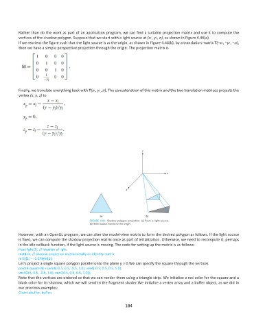
Rather than do the work as part of an application program, we can find a suitable projection matrix and use it to compute the
          vertices of the shadow polygon. Suppose that we start with a light source at (xl , yl , zl), as shown in Figure 4.46(a).
          If we reorient the figure such that the light source is at the origin, as shown in Figure 4.46(b), by a translation matrix T(−xl , −yl , −zl),
          then we have a simple perspective projection through the origin. The projection matrix is


          Finally, we translate everything back with T(xl , yl , zl). The concatenation of this matrix and the two translation matrices projects the
          vertex (x, y, z) to


          However, with an OpenGL program, we can alter the model-view matrix to form the desired polygon as follows. If the light source
          is fixed, we can compute the shadow projection matrix once as part of initialization. Otherwise, we need to recompute it, perhaps
          in the idle callback function, if the light source is moving. The code for setting up the matrix is as follows:
          float light[3]; // location of light
          mat4 m; // shadow projection matrix initially an identity matrix
          m[3][1] = -1.0/light[1];
          Let’s project a single square polygon parallel onto the plane y = 0.We can specify the square through the vertices
          point4 square[4] = {vec4(-0.5, 0.5, -0.5, 1.0), vec4(-0.5, 0.5, 0.5, 1.0),
          vec4(0.5, 0.5, -0.5, 1.0), vec4(0.5, 0.5, 0.5, 1.0)};
          Note that the vertices are ordered so that we can render them using a triangle strip. We initialize a red color for the square and a
          black color for its shadow, which we will send to the fragment shader.We initialize a vertex array and a buffer object, as we did in
          our previous examples:
          Gluint abuffer, buffer;

                                                             184