
Page 39 - GuardII+ Series 4208 Platform PD User Manual
P. 39
Installation
5.4. Preparation
Once unpacked, the PD card should remain for at least two hours at the place of
installation to ensure ambient temperature equalization and to prevent moisture condensation
before energizing.
5.5. Enclosure Cable Entry
Before installing the PD card, a new cable entry hole may need to be drilled into the
GuardII+ enclosure for the PD sensor cables. If the conduit is already run to the monitor, then
skip to Section 5.6. If new holes are required, refer to the GuardII+ Series 4208 Platform User
Manual for instructions on drilling these holes.
5.6. PD Card Installation
If the GuardII+ was purchased with the PD card installed, skip to Section 5.7.
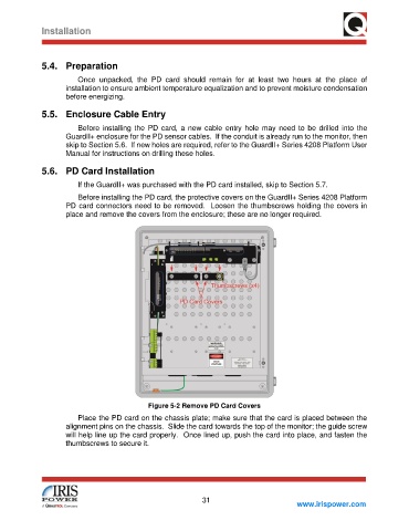
Before installing the PD card, the protective covers on the GuardII+ Series 4208 Platform
PD card connectors need to be removed. Loosen the thumbscrews holding the covers in
place and remove the covers from the enclosure; these are no longer required.
Figure 5-2 Remove PD Card Covers
Place the PD card on the chassis plate; make sure that the card is placed between the
alignment pins on the chassis. Slide the card towards the top of the monitor; the guide screw
will help line up the card properly. Once lined up, push the card into place, and fasten the
thumbscrews to secure it.
31
www.irispower.com