
Page 34 - GuardII+ Series 4208 Platform PD User Manual
P. 34
PD Card Operation
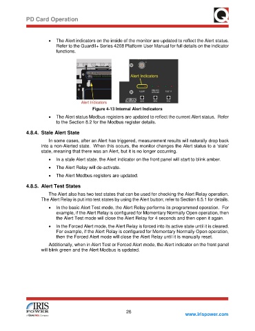
• The Alert indicators on the inside of the monitor are updated to reflect the Alert status.
Refer to the GuardII+ Series 4208 Platform User Manual for full details on the indicator
functions.
Figure 4-13 Internal Alert Indicators
• The Alert status Modbus registers are updated to reflect the current Alert status. Refer
to the Section 8.2 for the Modbus register details.
4.8.4. Stale Alert State
In some cases, after an Alert has triggered, measurement results will naturally drop back
into a non-Alerted state. When this occurs, the monitor changes the Alert status to a ‘stale’
state, meaning that there was an Alert, but it is no longer occurring.
• In a stale Alert state, the Alert indicator on the front panel will start to blink amber.
• The Alert Relay will de-activate.
• The Alert Modbus registers are updated.
4.8.5. Alert Test States
The Alert also has two test states that can be used for checking the Alert Relay operation.
The Alert Relay is put into test states by using the Alert button; refer to Section 6.5.1 for details.
• In the basic Alert Test mode, the Alert Relay performs its programmed operation. For
example, if the Alert Relay is configured for Momentary Normally Open operation, then
the Alert Test mode will close the Alert Relay for 4 seconds and then open it again.
• In the Forced Alert mode, the Alert Relay is forced into its active state until it is cleared.
For example, if the Alert Relay is configured for Momentary Normally Open operation,
then the Forced Alert mode will close the Alert Relay until it is manually reset.
Additionally, when in Alert Test or Forced Alert mode, the Alert indicator on the front panel
will blink green and the Alert Modbus is updated.
26
www.irispower.com