
Page 38 - GuardII+ Series 4208 Platform PD User Manual
P. 38
Installation
Note:
GuardII+ makes use of fasteners that are intended to be operated by hand;
only use hand tools for thumb screws and other hand-fasteners. Over
tightening will cause damage to the monitor.
• All cable entries into the box should be located as specified in the GuardII+ Series
4208 Platform User Manual.
• Signal and communications cables shall run along grounded metal surfaces like metal
conduits, metal trunking or ducts, preferably away from power cables. They should
not run on open trays alongside power cables.
• The conduits shall be installed with insulated fixings as required to ensure grounding
only at one end. For conduit sizes follow the local electric codes.
• Shielded cables should have the shield grounded only at one end of cable segments
to avoid circulating currents through the shield.
5.2. Sensor Termination Boxes
PD sensors for a GuardII+ require a separate sensor termination box. Refer to the
appropriate sensor Installation guides for instructions to install the sensors and termination
box.
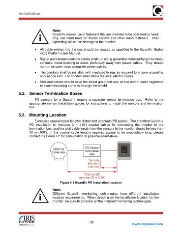
5.3. Mounting Location
Excessive coaxial cable lengths distort and attenuate PD pulses. The standard GuardII+
PD installation kit includes 3 m (10’) coaxial cables for connecting the monitor to the
termination box, and the total cable length from the sensors to the monitor should be less than
30 m (100’). If the coaxial cable lengths required appear to be unavoidably long, please
contact Iris Power LP for consultation or possible alternatives.
Figure 5-1 GuardII+ PD Installation Location
Note:
Different GuardII+ monitoring technologies have different installation
location requirements. When deciding on the installation location for the
monitor, be sure to consider all the installed monitoring technologies.
30
www.irispower.com