Page 42 - GuardII+ Series 4208 Platform PD User Manual
P. 42

Installation


              5.8.  PD Sensor Connections

                        The GuardII+ PD inputs are connected to the PD sensor termination box  with coaxial
                     jumper cables; a set of 3 m (10’) cables are provided in the installation kit.

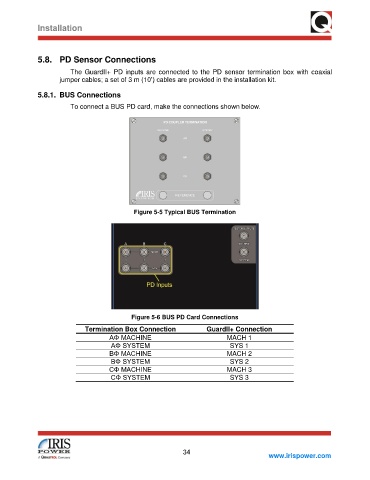
              5.8.1.  BUS Connections
                        To connect a BUS PD card, make the connections shown below.


                                             Figure 5-5 Typical BUS Termination


                                            Figure 5-6 BUS PD Card Connections
                             Termination Box Connection              GuardII+ Connection
                                     AΦ MACHINE                             MACH 1
                                      AΦ SYSTEM                              SYS 1
                                     BΦ MACHINE                             MACH 2
                                      BΦ SYSTEM                              SYS 2
                                     CΦ MACHINE                             MACH 3
                                      CΦ SYSTEM                              SYS 3


                                                              34
                                                                                          www.irispower.com
   37   38   39   40   41   42   43   44   45   46   47