
Page 1061 - 2006 HARLEY FLSTCI SERVICE MANUAL
P. 1061
8.15
T27 TORX screw @55-75 in-lbs (6.2-8.5 Nm)
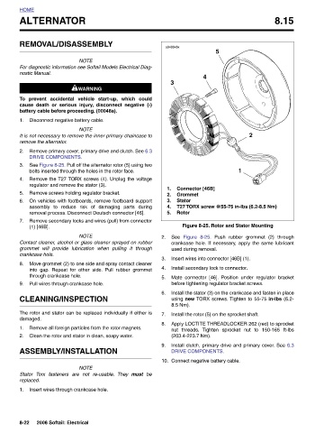
Figure 8-25. Rotor and Stator Mounting crankcase hole. If necessary, apply the same lubricant Mate connector [46]. Position under regulator bracket Install the stator (3) on the crankcase and fasten in place using new TORX screws. Tighten to 55-75 in-lbs (6.2- Apply LOCTITE THREADLOCKER 262 (red) to sprocket Install clutch, primary drive and primary cover. See 6.3
2 Push rubber grommet (2) through Tighten sprocket nut to 150-165 ft-lbs
1
5 before tightening regulator bracket screws. Install the rotor (5) on the sprocket shaft.
Connector [46B] Grommet Figure 8-25. used during removal. nut threads. (203.4-223.7 Nm). DRIVE COMPONENTS.
4 Insert wires into connector [46B] (1). Install secondary lock to connector. Connect negative battery cable.
s0488x8x 3 1. 2. Stator 3. 4. Rotor 5. See 8.5 Nm).
2. 3. 4. 5. 6. 7. 8. 9. 10.
be
assembly to reduce risk of damaging parts during
Move grommet (2) to one side and spray contact cleaner
into gap. Repeat for other side. Pull rubber grommet
Remove secondary locks and wires (pull) from connector
Remove primary cover, primary drive and clutch. See 6.3
prevent accidental vehicle start-up, which could
See Figure 8-25. Pull off the alternator rotor (5) using two
On vehicles with footboards, remove footboard support
Remove the T27 TORX screws (4). Unplug the voltage
must
They
ALTERNATOR REMOVAL/DISASSEMBLY NOTE For diagnostic information see Softail Models Electrical Diag- 1WARNING 1WARNING cause death or serious injury, disconnect negative (-) battery cable before proceeding. (00048a). Disconnect negative battery cable. NOTE It is not necessary to remove the inner primary chaincase to remove the alternator. DRIVE COMPONENTS. bolts inserted through the holes in the rotor face. regulator and remove the stator (3). Remove screws holding regulator bracket. removal process. Disconnect Deutsch connector [46]. NOTE Contact cleaner, alcohol or glass cleaner sprayed on rubber grommet will provide lubrication when pulling
HOME nostic Manual. To 1. 2. 3. 4. 5. 6. 7. (1) [46B]. crankcase hole. 8. 9. damaged. 1. 2. Stator replaced. 1. 8-22